Metal materials missing that little bit of zing? Check out Francesco Furneri’s guide to rendering realistic metals and some practical tips for Substance Painter.
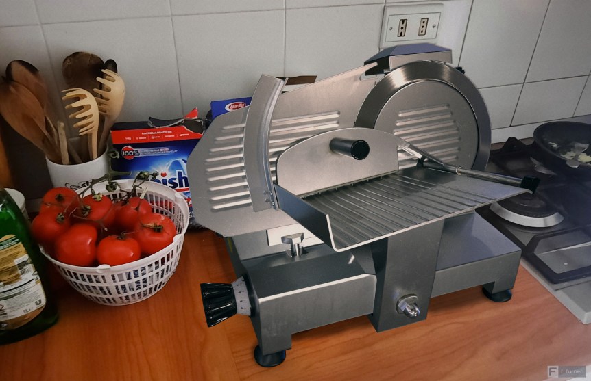
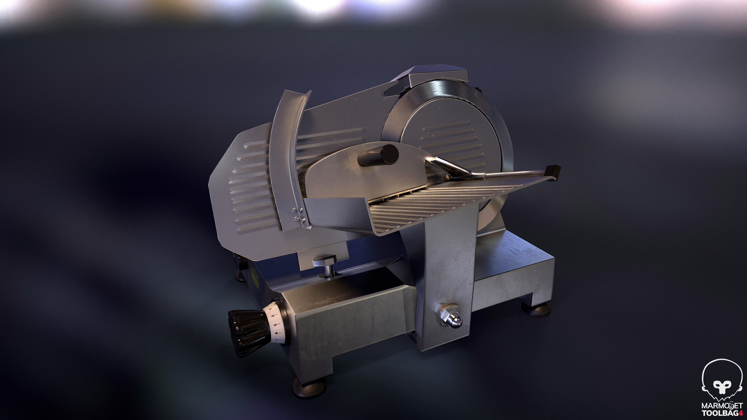
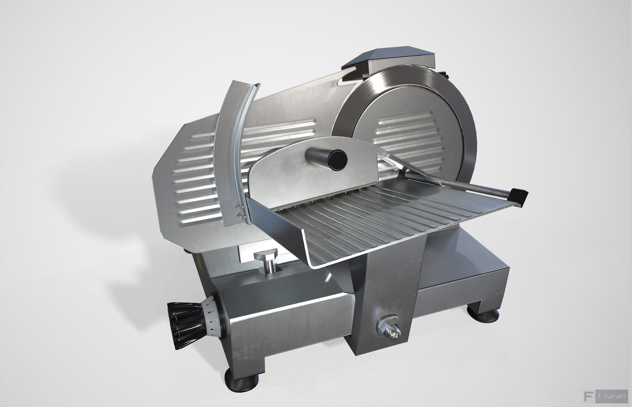
In this article, you’ll learn how to create realistic metal materials and, in particular, I’ll give you some tips on producing different types of realistic details in Substance Painter. For the purpose of this article, let’s consider a project that you can find at my Artstation page, which shows a perfect example of a metal object enriched by micro details such as dirt, scratches, dust, and so on.
Before getting into the whole topic, let’s see in a nutshell what makes metal so different from other types of material.
Metals are electrical conductors and– as opposed to insulators— reflect more incoming light, absorbing some wavelengths. Phenomena like diffuse reflections are practically non-existent here because of the free charges, which prevent light from getting inside the material and causing diffusion / scattering.
On the other side, the absorption of certain wavelengths gives metal a tinted color that is typical of these materials and the reflection is evident even if we observe the object perpendicularly to the surface (at Fresnel zero).
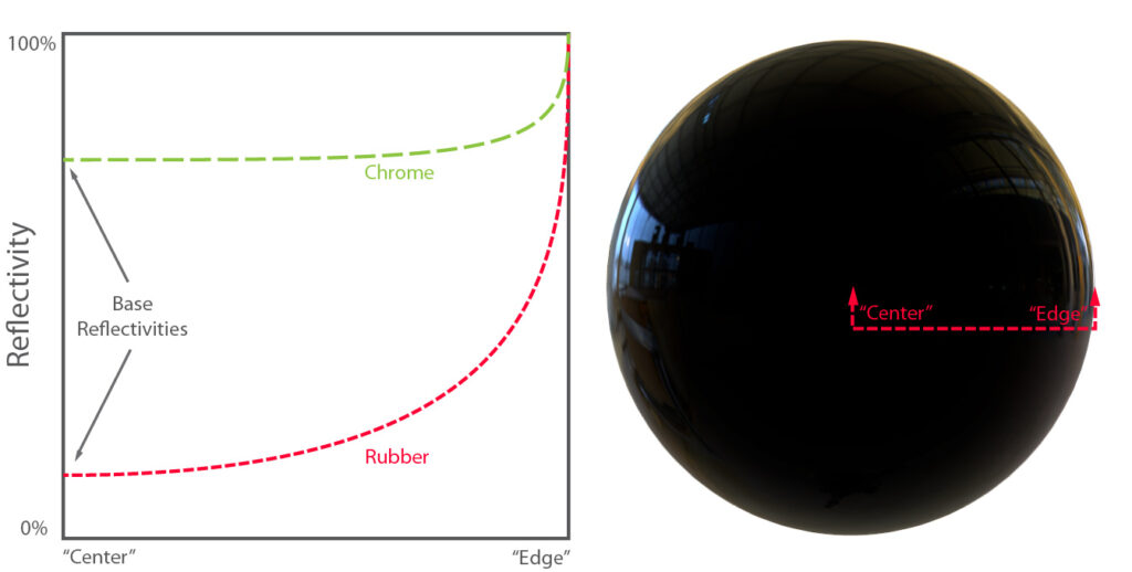
In insulators– for instance, rubber– the reflection is low at the “Center” (Fresnel zero) but becomes stronger at the “Edge”; whereas metals behave differently, with around 70% of reflectivity at the “Center.” (For more info about PBR materials for metals, refer to the awesome PBR Guide – Part I by Adobe._
Discovering Details On Metal
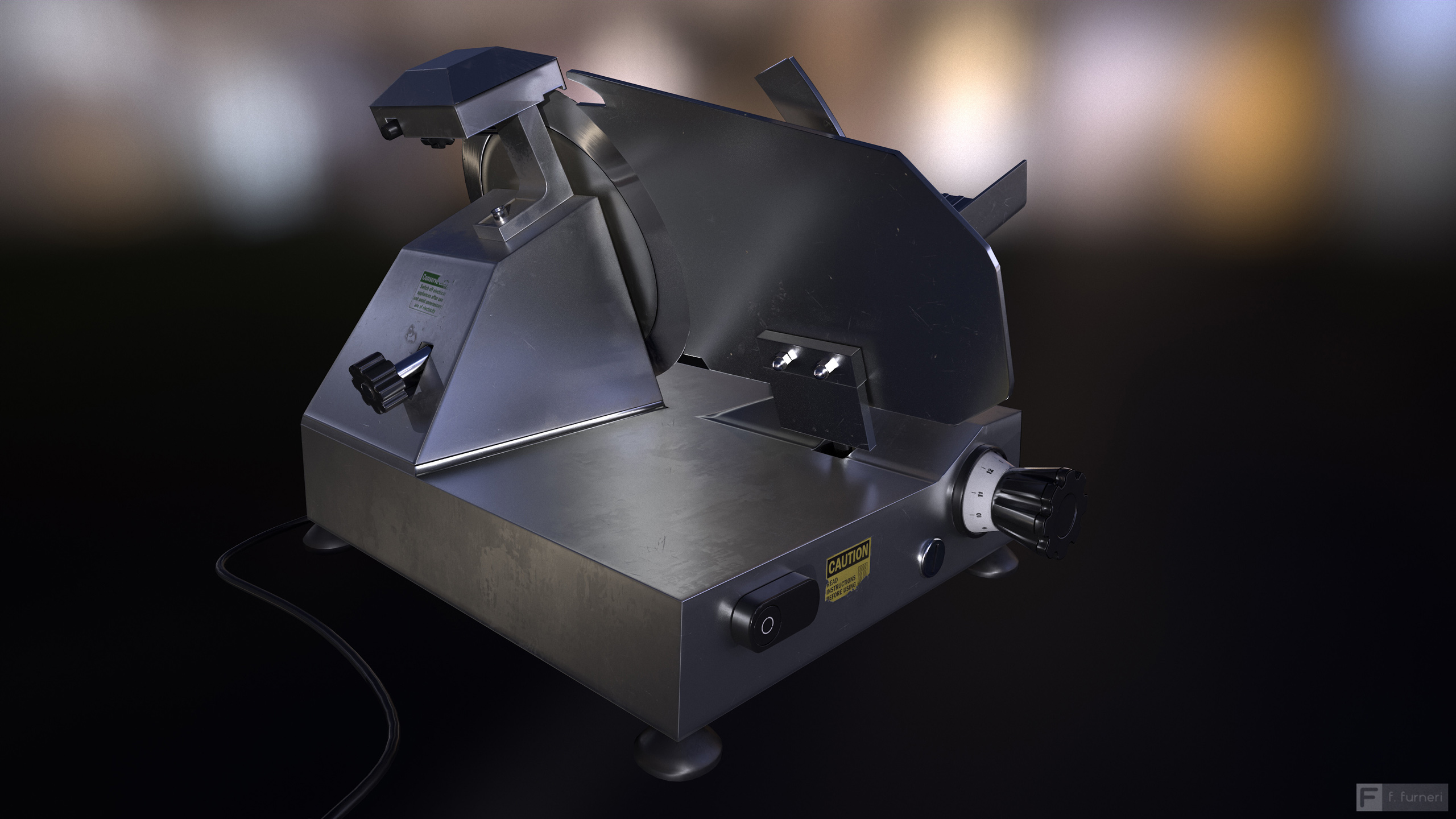
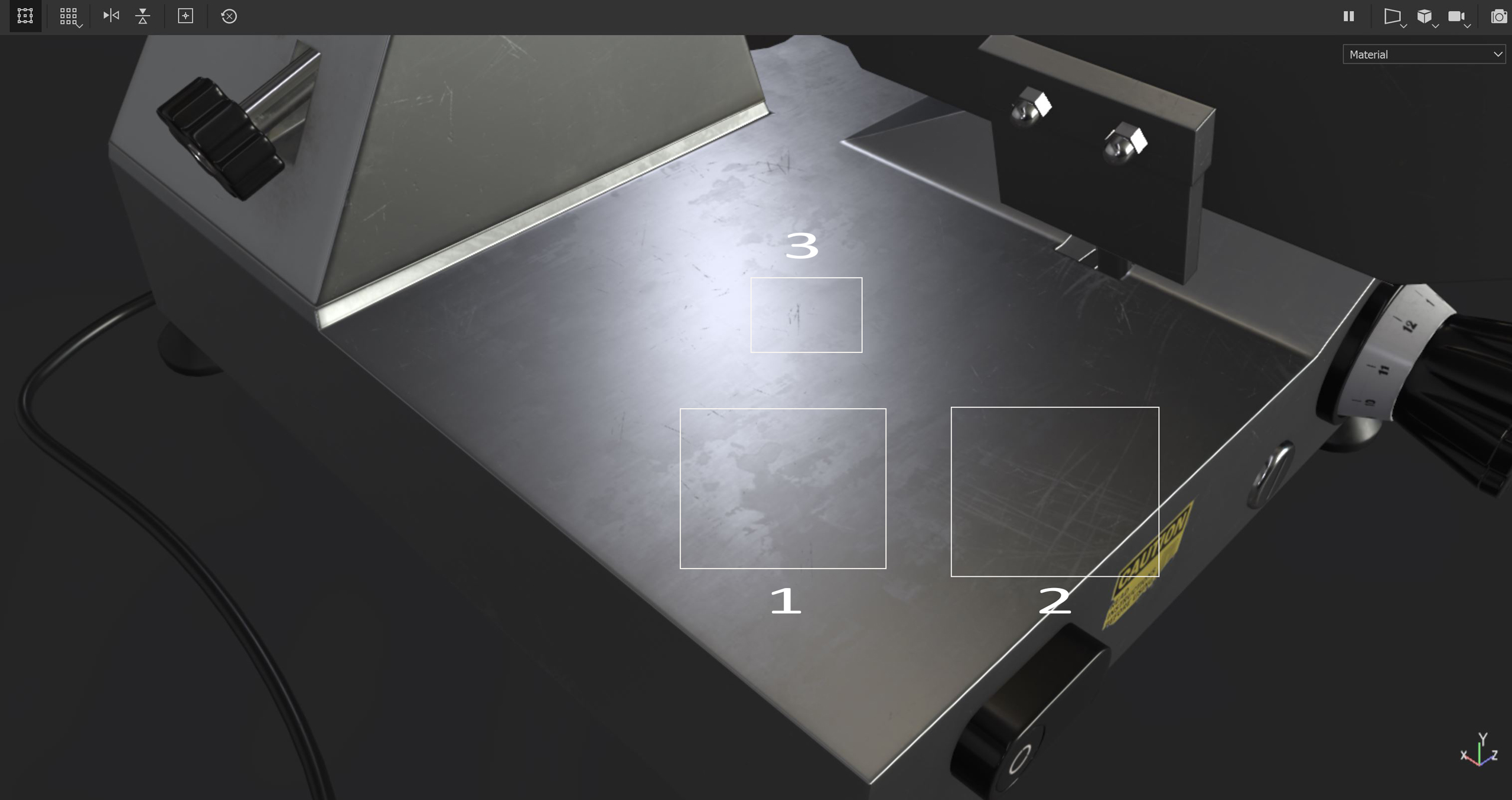
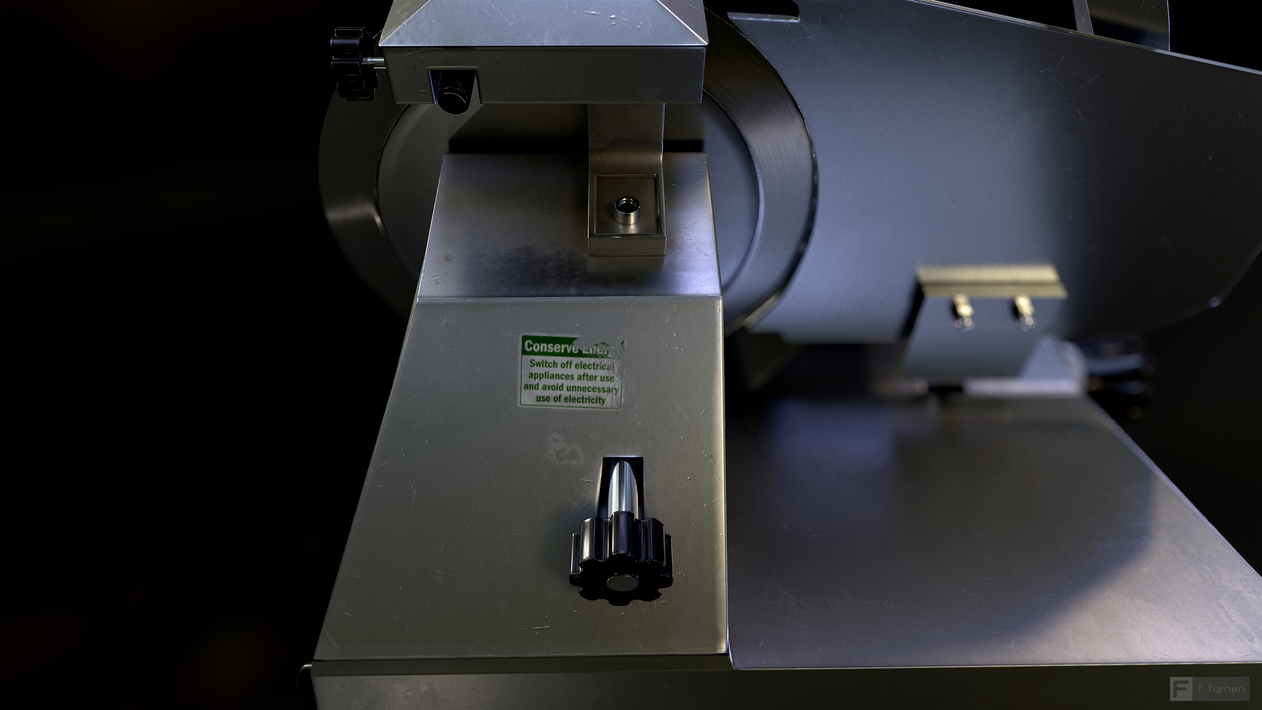
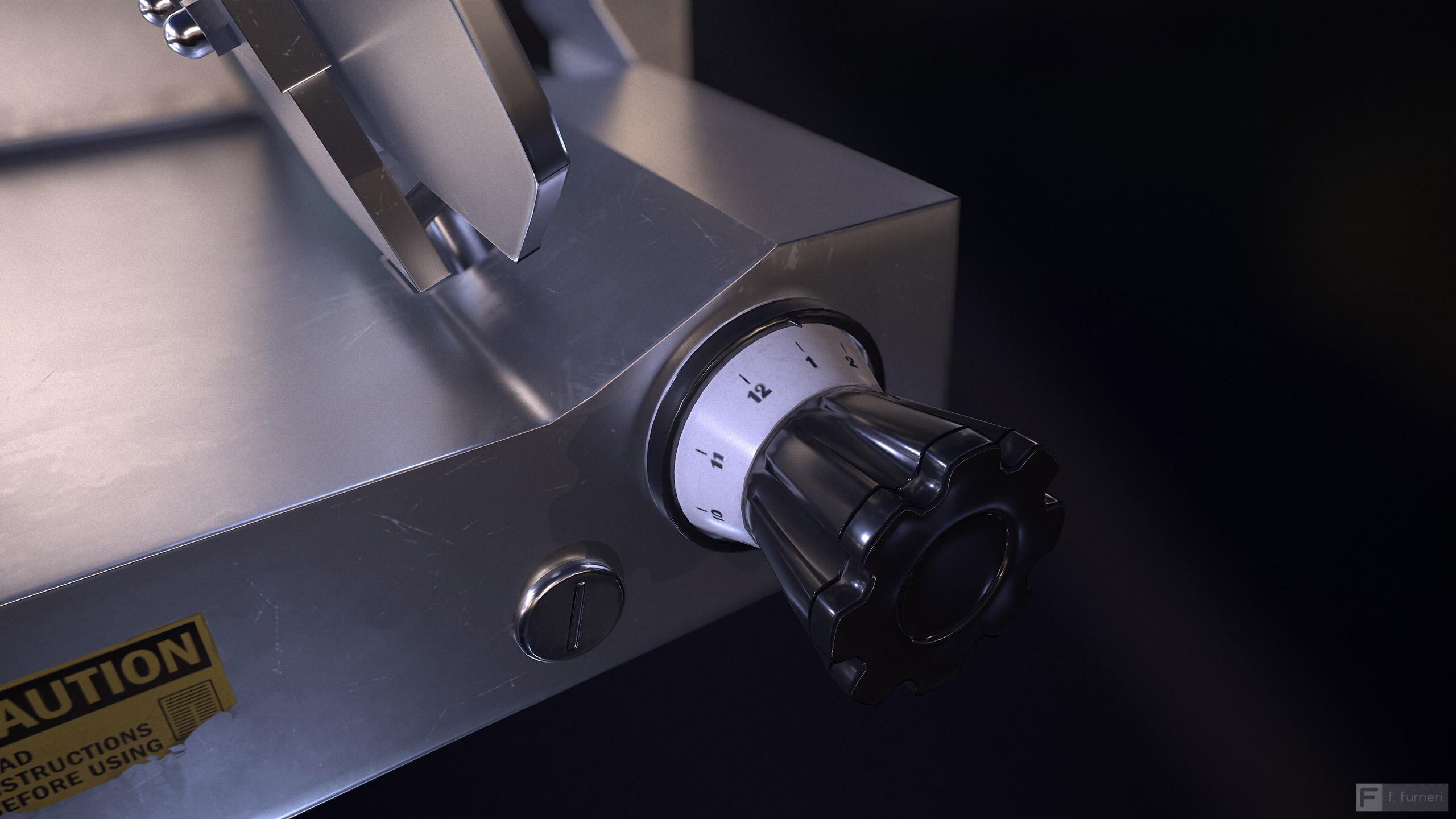
The slicer material, as a whole, might look basic, but with a closer look, there are many small details that are worth considering.
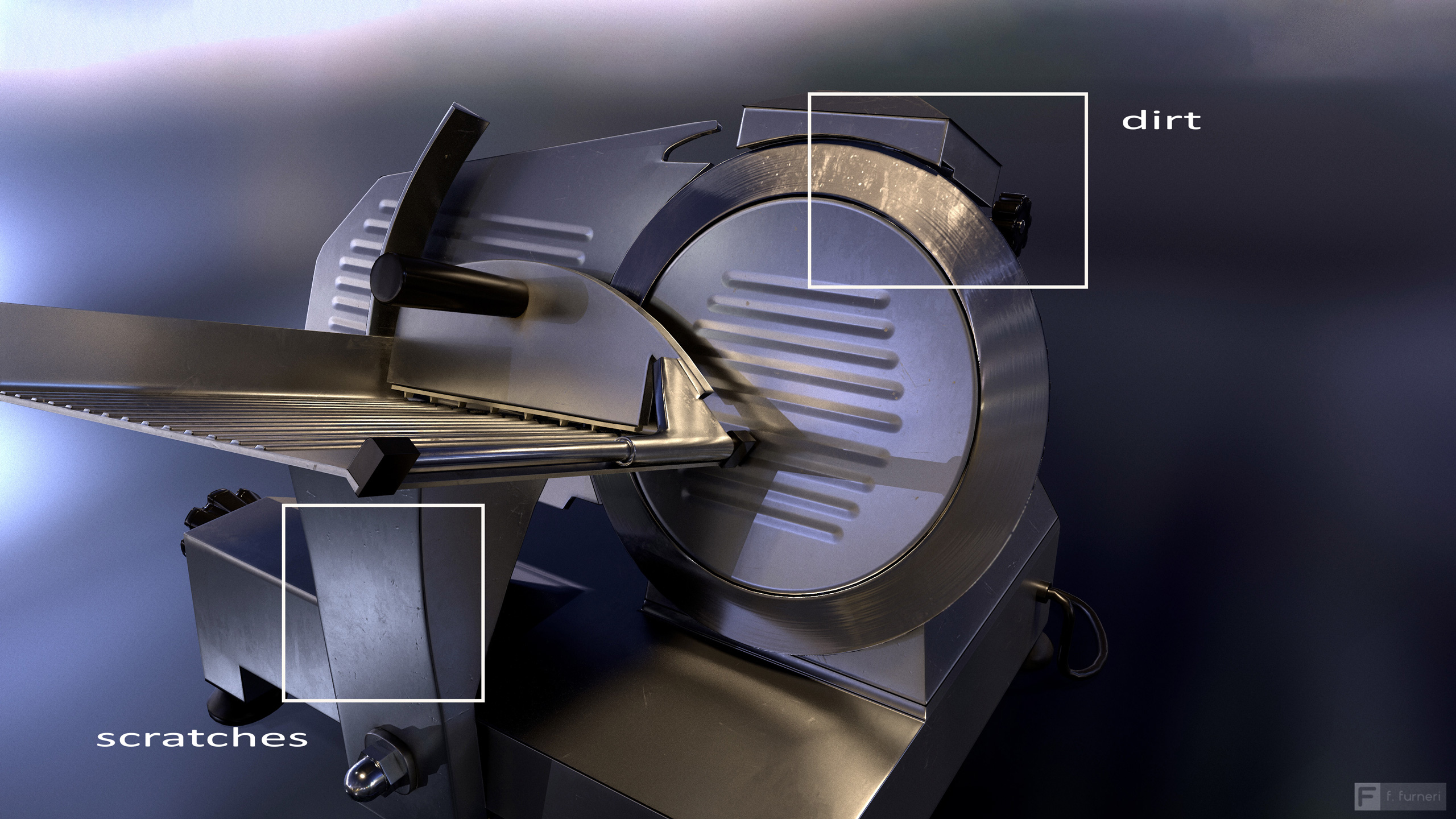
By observing real metal objects, you’ll be surprised by the myriad of micro elements and details which appear on the surface. Let’s cite a few examples:
- Scratches: in some areas, especially when metal utensils or simply a steel sponge rub against the surface. I tried to insert some scratches throughout the model but without exaggerating too much.
- Stains / dirt: you’ll notice on the blade part that there’s very thin layer of dirt; this effect is also observable when a detergent is mixed to with water and small dirt particles dry off, leaving residue as result.
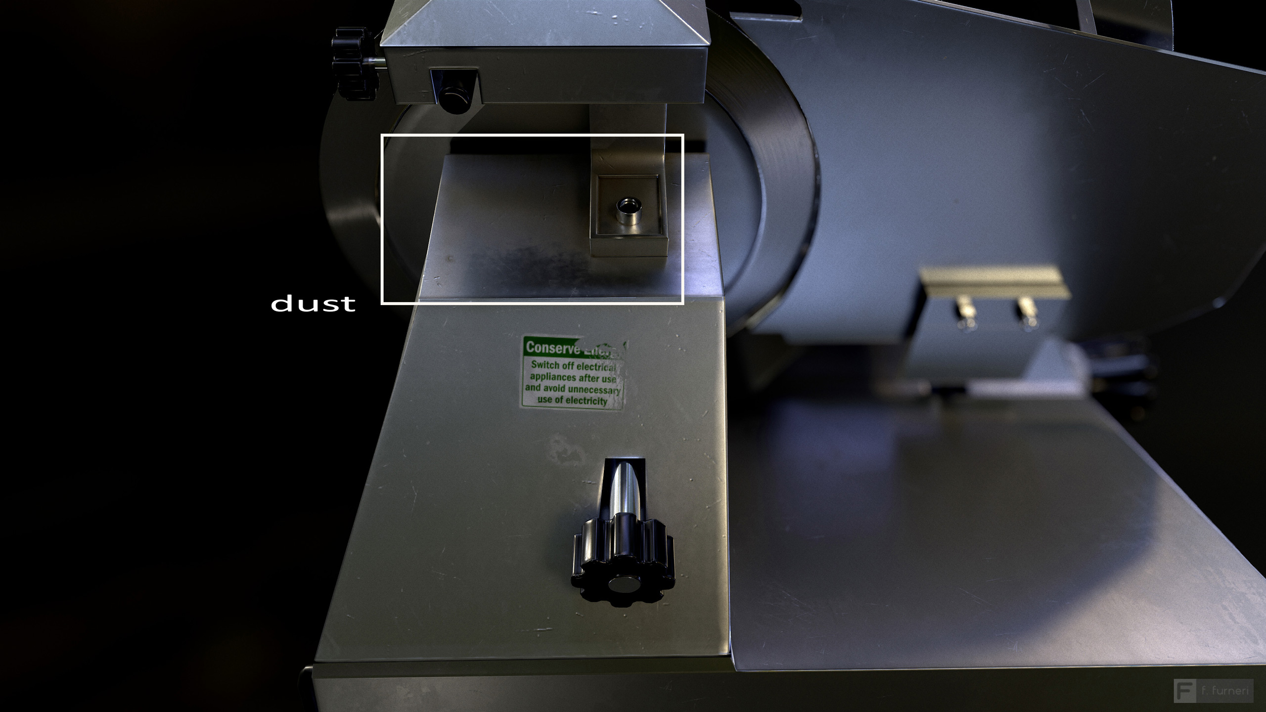
- Dust: located in the back of the slicer, dust consists of both semi-transparent and thicker layers, in order to randomize the effect and its distribution.

Generally speaking, most of the slicer surface is covered by a steel layer, with the presence of small random stains, to make the material more interesting.
Finally, I looked in on my reference images to discover that many meat slicers have the blade material with a different type of reflection, compared to the rest: that’s a clear example of anisotropic reflections.
If the word “anisotropic” sounds intimidating, don’t worry!! I’ll explain that in a bit.
Some reflective surfaces are made of small fibers or tiny bumps and scratches and they follow a specific direction, rather than being random on a surface. Think about brushed metals or simply hair; when light hits their surface, the reflection appears to be stretched along a well determined direction.
As general rule, this direction is always perpendicular to the direction of the bumps / fibers. That always happens with anisotropic reflections: for instance, hair has vertical fibers, but the reflections are horizontally elongated.
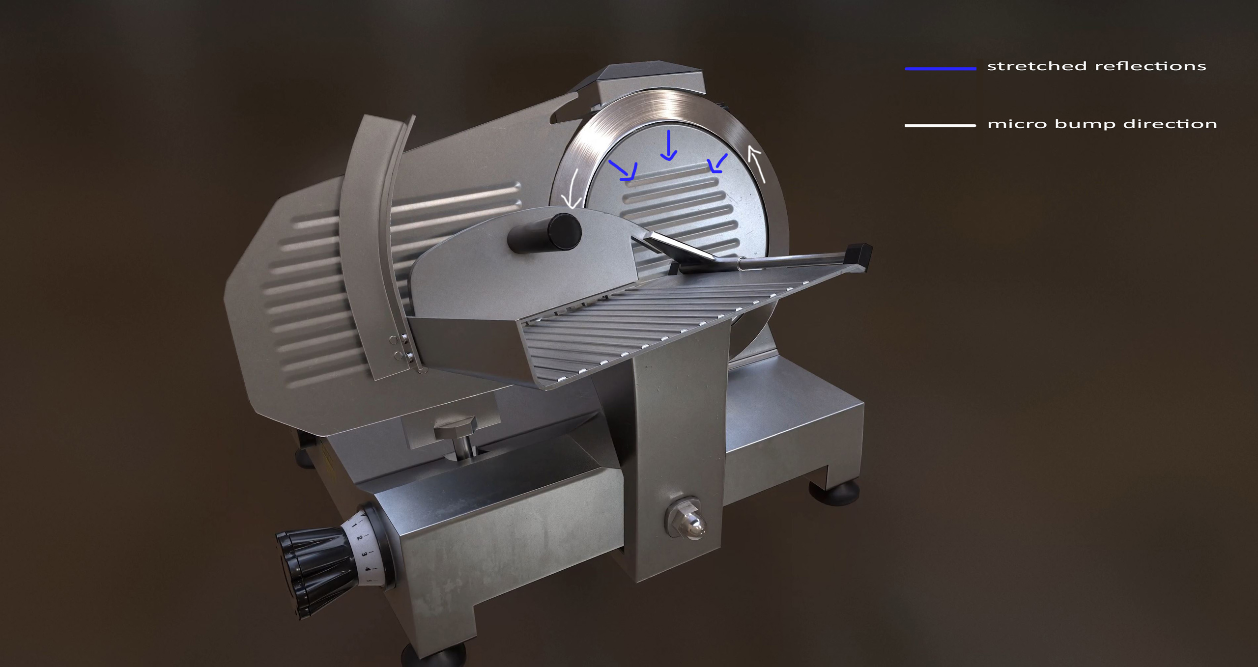
If the blade had been not just the external part but the entire wheel, we would have observed the reflection following the blue arrow direction towards the center, in the same way a kitchen pot produces a cone-shaped anisotropic reflection.
From Observation To Practice
This part is about Substance Painter, an industry standard for material authoring. In particular, we’ll just look at a few examples that will guide you through the creation of some materials.
Note that this won’t show the entire texturing process from scratch, just some techniques and good practices to translate your ideas into compelling PBR materials.
Furthermore, if you have never used Painter in your projects, I suggest that you have a quick look at concepts like paint and fill layers, procedural maps, generators, filters, and masks and materials, which will be mentioned in the next part.
Basic Structure
When I approach texturing, I often start with very basic presets which are simply called Materials in Painter; this allows me to have some parameters to work with and options to apply.
From there, I build my complex material by using layers, which remind of layers in Photoshop but with a different workflow.
The basic structure is made of the following layers:
- The Base Iron which uses the Iron Rough preset
- The Scratches layer
- The Small Scratches layer
- The Yellow Label layer, which won’t be discussed here
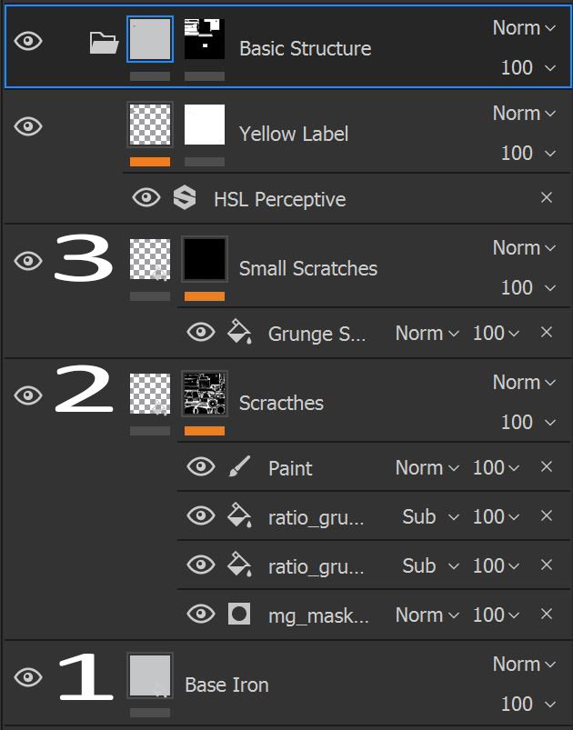
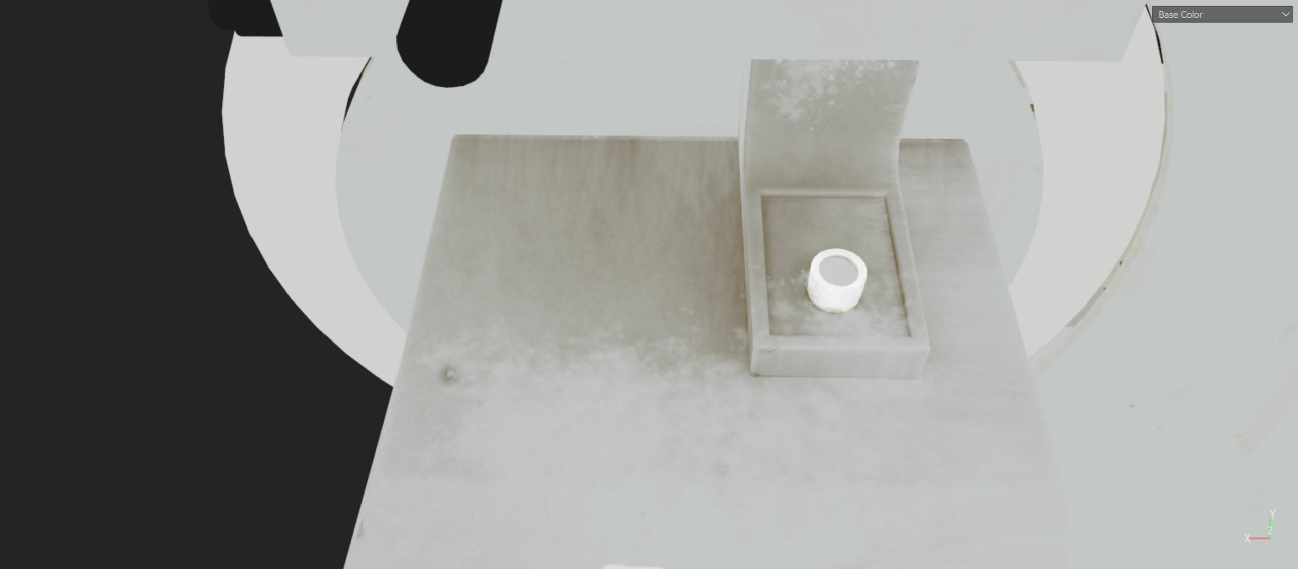
In the Base Iron (1), I chose a proper color (gray) and the roughness is set to 0.2; the cool thing about this material is related to the Finish rollout in the material properties, which allows me to add those random stains we talked about.
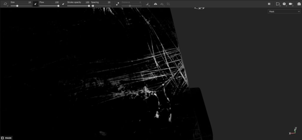
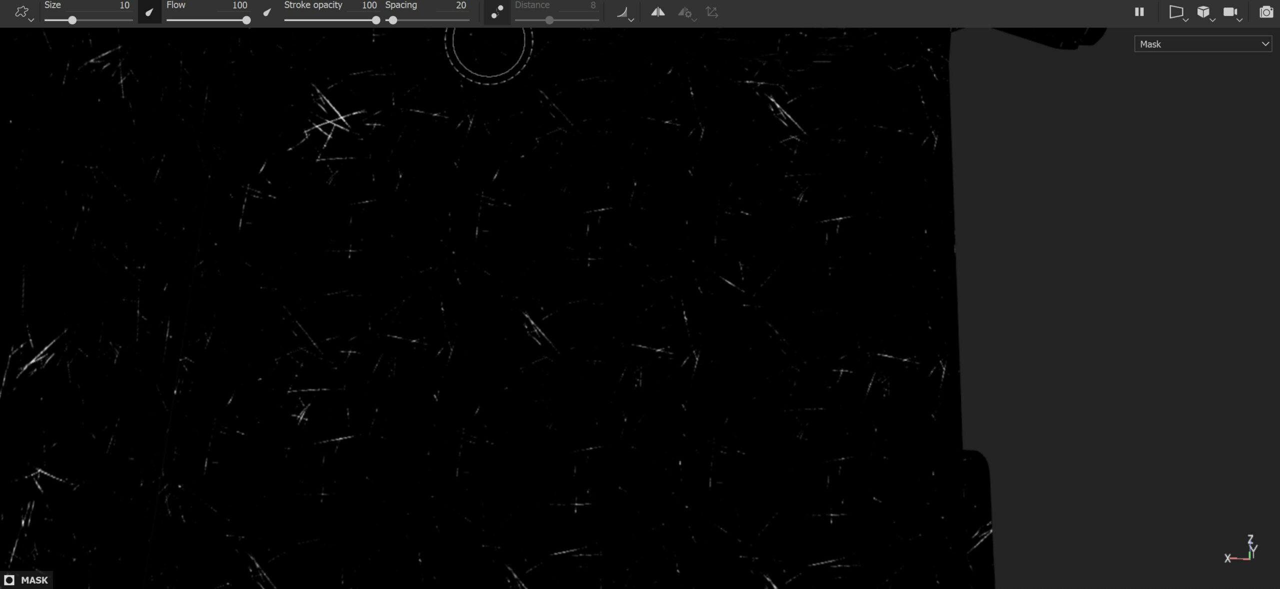
One of the techniques I use in Painter while adding details is based on mask creation. First, I decide what maps to include in the current layer (base color, roughness, etc.) and then I build the complex mask. This is what happens in the Scratches layer (2): I worked on base color and roughness by setting their values, then I revealed those values in the mask.
The mask is not just the result of a simple grayscale procedural map; it’s made by 1 generator, 2 fill layers, and 1 paint layer which are blended together. The paint layer was used to manually delete part of the mask where we don’t want the roughness and the color values to be shown.
The Small scratches layer (3) uses the same approach as 2 but with a simpler mask. This time I used a procedural grunge map called “Grunge Scratches Rough,” which comes with Painter, and I adjusted the scale, the scratch quantity and tiling, etc.
The channels/maps shown in the mask are the roughness, base color, and the height, which I increased just a tiny bit.
Dust Effect
In the slicer, there are areas where I introduced some dust, but there is one in particular that I would like to discuss here.
The technique I used here is similar to the previous one: I create a mask for the dust area and I used it to reveal my maps (base color, roughness, and metallic) but let’s make a digression first by explaining the importance of metal areas partially covered by an insulator (dust).
When working with PBR materials, with a metal / roughness workflow, you have to deal with a metallic map, where white values indicates raw metal and black values, non-metal. If the dust is not thick enough to totally obscure the metal underneath (you achieve that by reducing the opacity of the dust color), part of the visible metal reflection is reduced in intensity because of the insulator (dust) while the metallic map would store some grayscale values in the corresponding dust area.
PS. If the values in the metallic map are within the interval (0,1), remember to check the reflectance values in the base color as well. A good practice is to lower the reflectance values in the base color when the metallic map goes towards black values: consider that reflectance of raw metals varies between 70-100% ( corresponding to 180-255 sRGB in the base color); if we go below 70%, the reflectance values in the base color have to be lower as well. That creates a smooth blend between metal and non metal parts.
This reasoning is valid for insulators which partially occlude metals, but in case you had a perfectly opaque material (insulator) covering the metal part, its corresponding values in the metallic map would be exactly equal to 0 and not an in-between: think about a paint layer as an insulator, which hides the raw metal of a car.
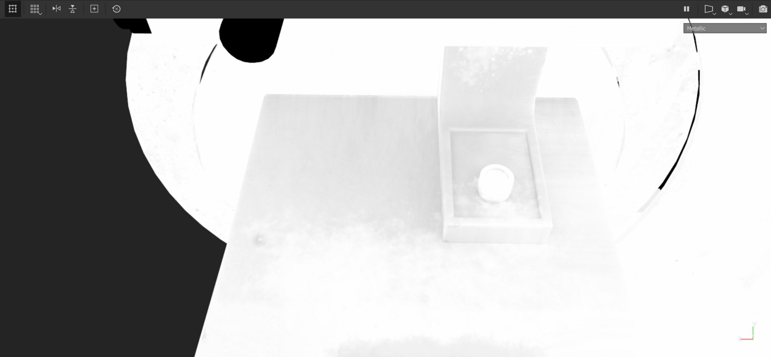
For our slicer, here is the metallic map: see that the area related to the dust is not completely white for the reasons we have just explained.
For the insulator part (the dust), I also increased its roughness to make it more realistic and chose the following brown color:
Let’s get back to our material. How did I paint and generate the maps involving the dust? Let’s see it right now.
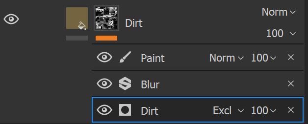
Here’s how I created a layer with a brown color, a high roughness (0.8), and the metallic part.
To show the previous info (color, roughness and metal) I created a custom mask; you can use bitmaps, procedural maps, or you can even paint on parts of the model.
For the dust, I experimented with a Dirt Generator. The difference between a generator and a normal bitmap / procedural map used as mask is interesting: the former creates the mask based on custom parameters and additional baked maps, while the latter simply utilizes an image and some parameters.
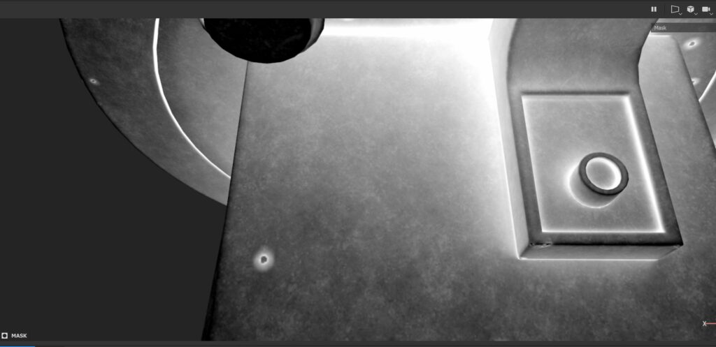
For instance, if we create a curvature map, storing convex and concave areas of a model, we can use it as input in our generator: since the dirt / dust tend to accumulate in recessed areas, the curvature map tells the generator where to find concave parts and thus where to mask less.
I also used an ambient occlusion map to guide the effect.
The result is great!! See the areas around the corner; there we have more dust as expected.
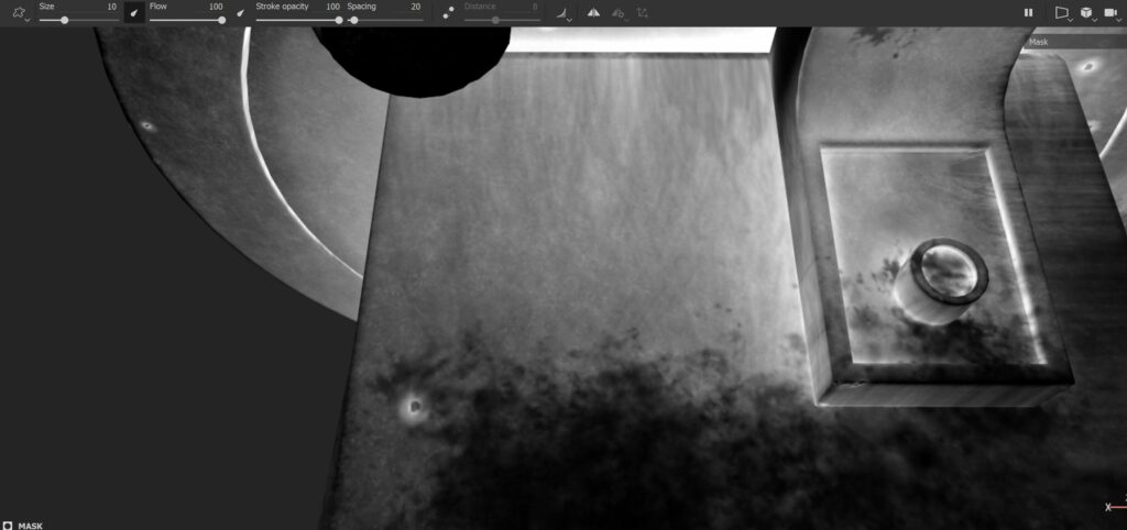
I used a Blur effect to smooth the mask a bit.
Finally I decided to apply a paint layer to manually modify the mask and here is the result
Anisotropic Reflections
In this part we’ll discuss how to achieve an anisotropic effect in Substance Painter.
To enable Anisotropic reflections, you initially have to add a couple of channels in your texture set settings: they are called Anisotropy level and Anisotropy angle.
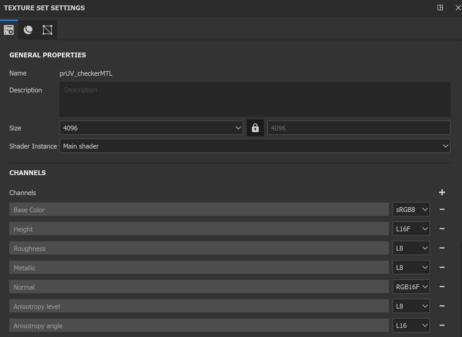
Think about Anisotropy level as the length / strength of our reflection and the Anisotropy Angle, which uses an angle map instead of a direction map, as a way to indicate the orientation of our grooves.
This is the base setting for our anisotropic reflections.
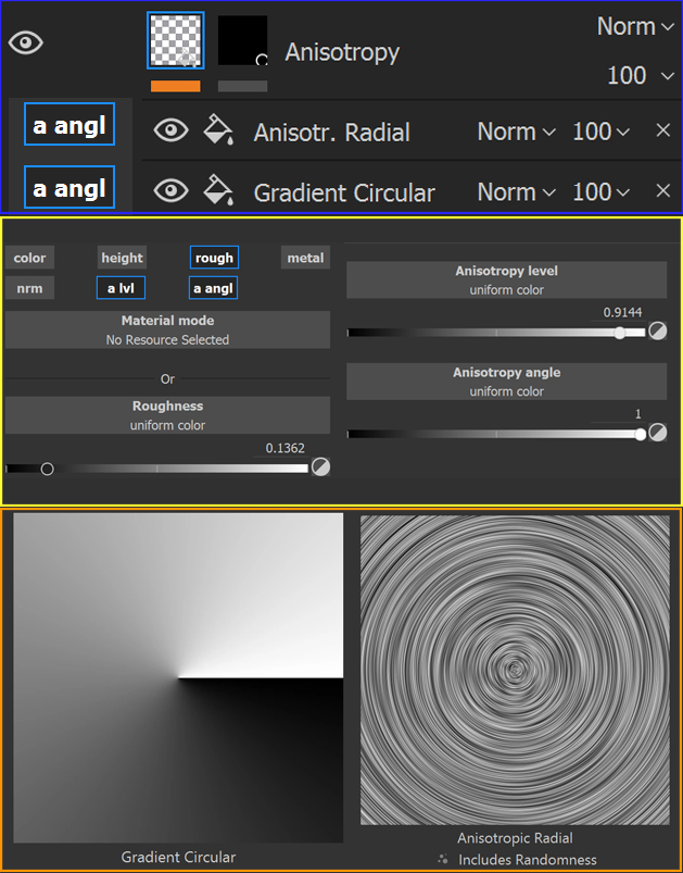
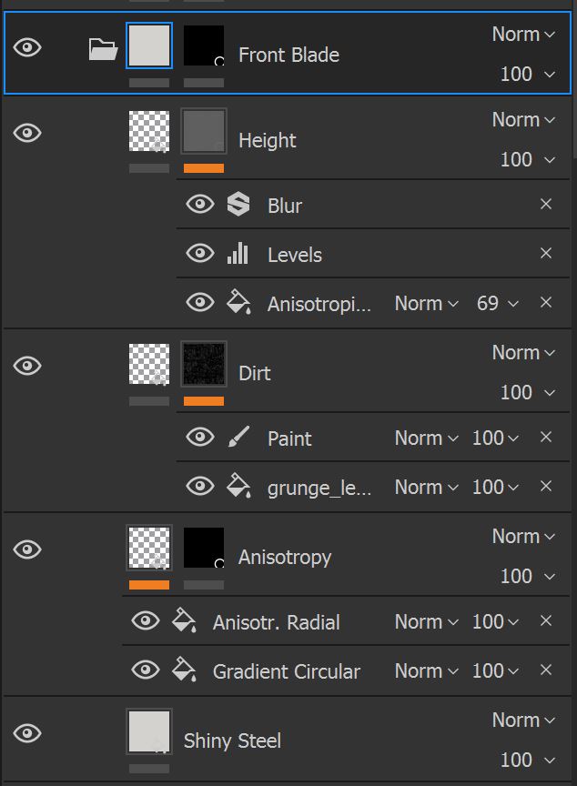
- The blue section shows the layer: it has a mask to limit the effect to the blade and 2 layers, which are part of the main material and not part of the mask. They are Anisotropic Radial and Gradient Circular: they both store maps for the Anisotropic Angle channel.
- The orange rectangle shows the 2 maps in detail, describing the orientation of the grooves along the blade.
- The yellow rectangle, finally, refers to the main Anisotropy layer. It sets the roughness, the Anisotropy level and practically enables the Anisotropic angle for the previous 2 maps.
The use of the 2 textures for the grooves implies that you have a UV mapped model of your object, which follows a circular shape.
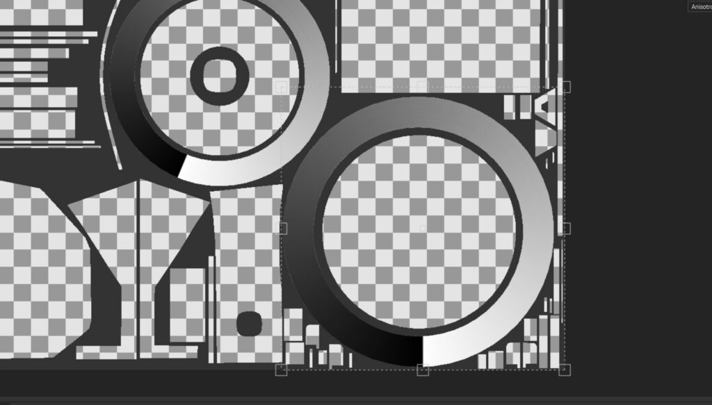
We won’t describe the rest of the details on the blade but I’ll show you a quick example of what I produced for the Front Blade:
- A Shiny Steel layer used as base
- Our previous Anisotropy layer
- A Dirt layer, with a mask created by a Grunge map and a Paint layer
- A Height layer which gives a bit of depth to the grooves
The front Blade is then ready!
Tips for Rendering
In this last part, I’ll give you some tips on how you can easily render your piece. In this project, I used Marmoset Toolbag 4 but you can use the 3D renderer of your choice.
1. Choose a proper HDRI map and use additional lights
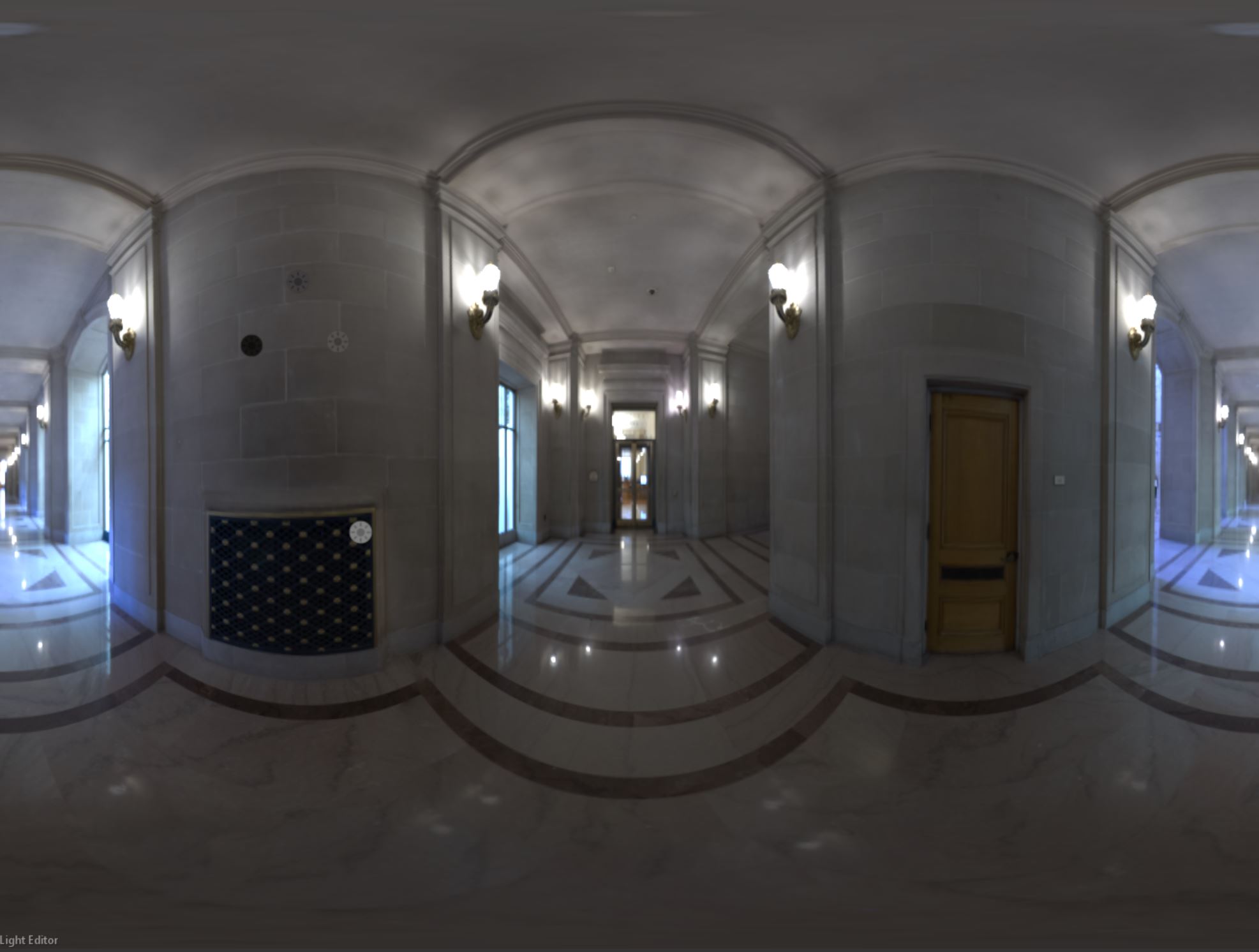
HDR images are always a great choice and much more for metals, where reflections play an important role. Don’t try the first image but dig into external resources like https://polyhaven.com/ or even Marmoset itself has a awesome pre selection of HDRI images ready to use.
Rotate your HDRI map around your model, until you are satisfied with your reflections.
For my renders I experimented with different HDRI maps of indoor and outdoor environments: I looked for images with a bit of contrast and some with artificial lights, which helped me capture some sharp reflections.
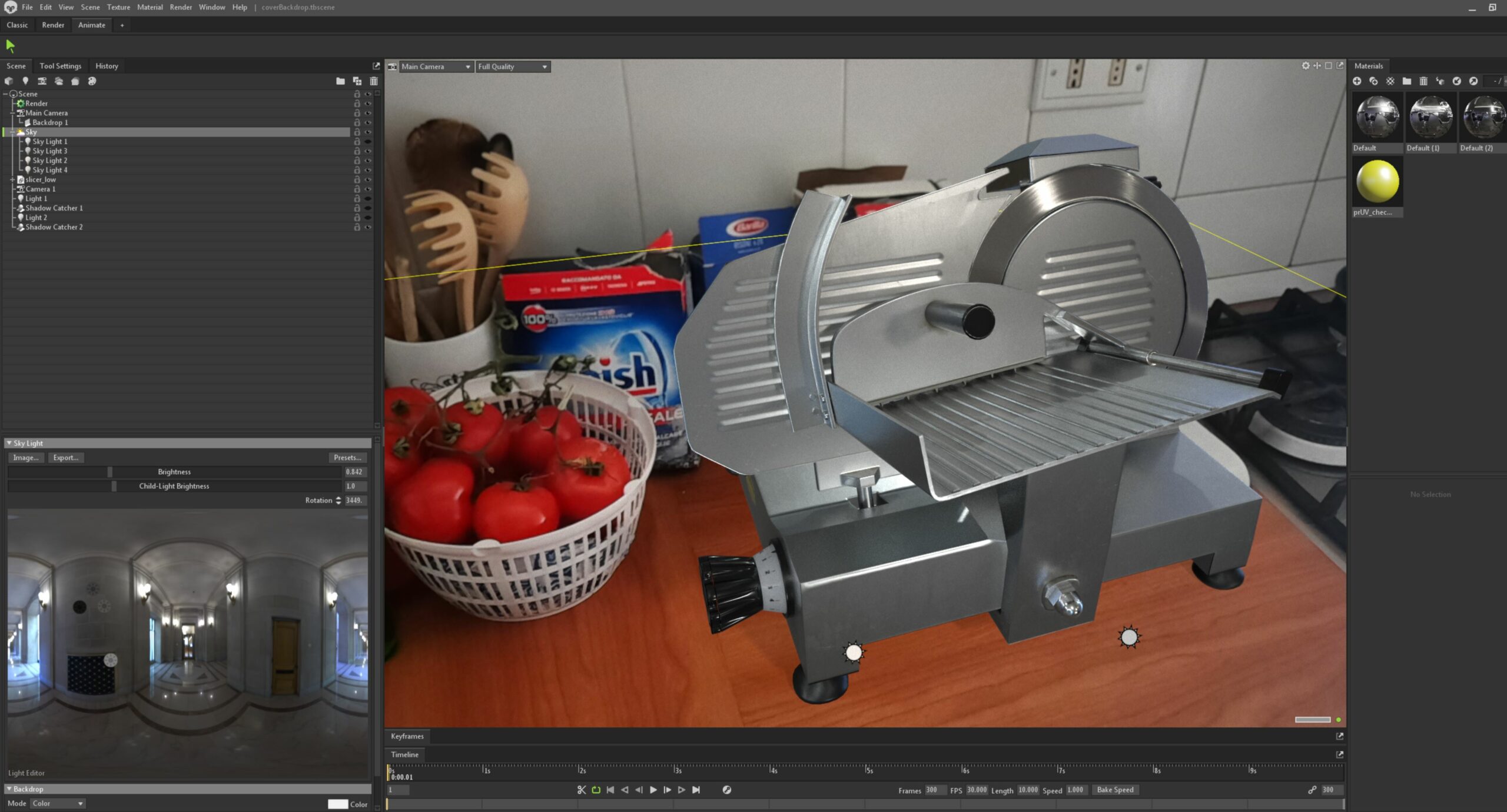
Note that the HDRI map might be sufficient to light your model but sometimes you might need additional light sources to add additional reflections.
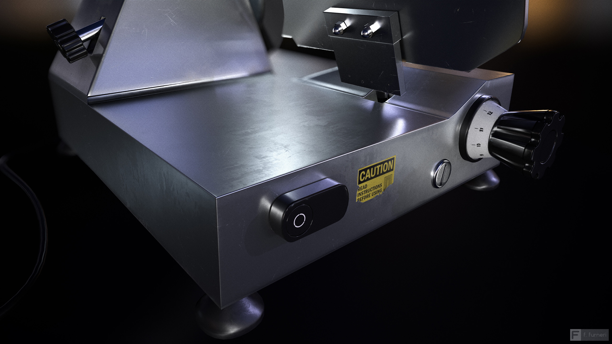
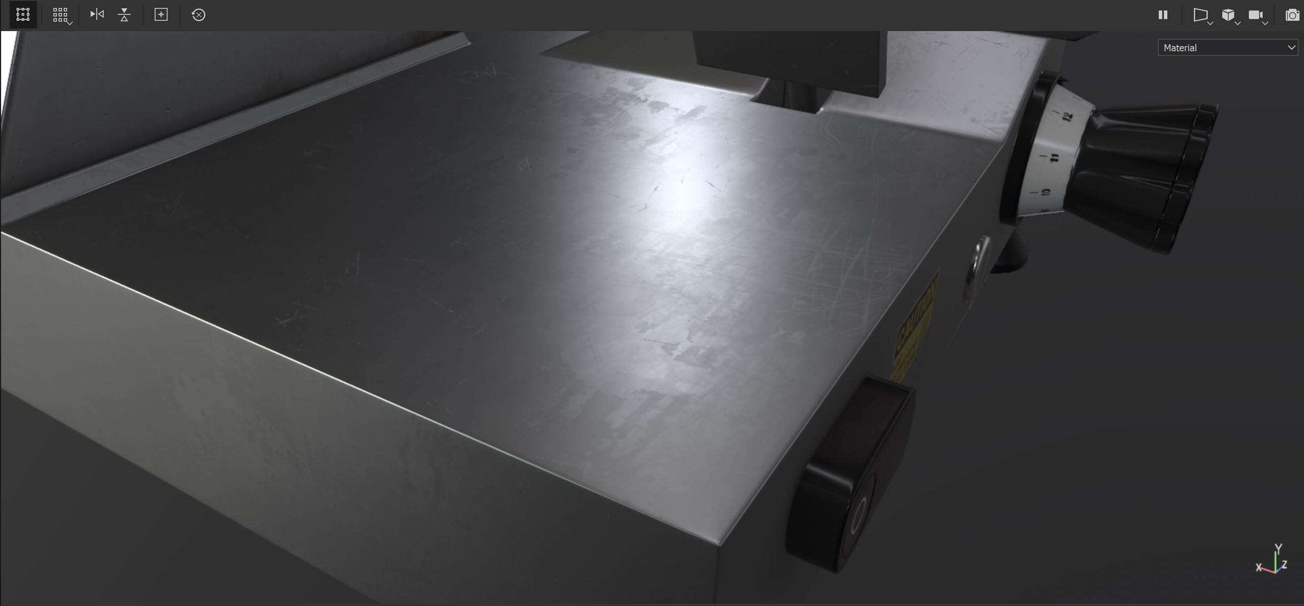
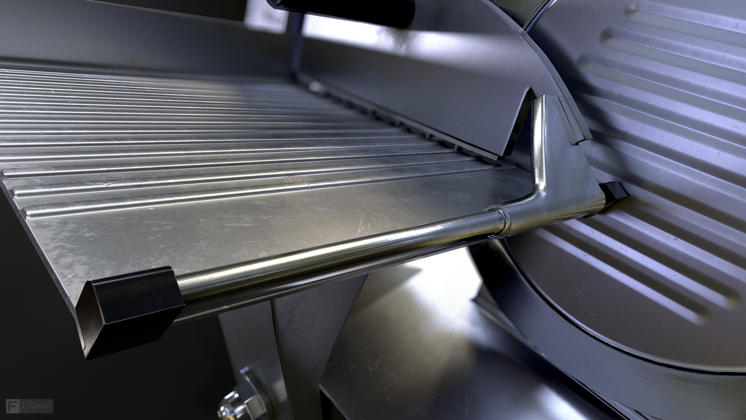
2. Produce close ups and add depth of field
I personally love to capture details in my works with a high zoom, like in the following renders: the idea is to have something that catches your eye like an area with dust, some scratches here and there and so on.
I also introduced some depth of field to make the result more realistic.
3. Convey a mood with color schemes
You can create harmony in your scenes by choosing the right colors.
Complementary colors, for instance, make your composition stronger: if you want to give a more artistic look to your renders you can see my choice in one of the slicer render.
Here I chose 2 complementary colors (blue and orange) being reflected by the metal surface: they are subtle but nice for the composition.
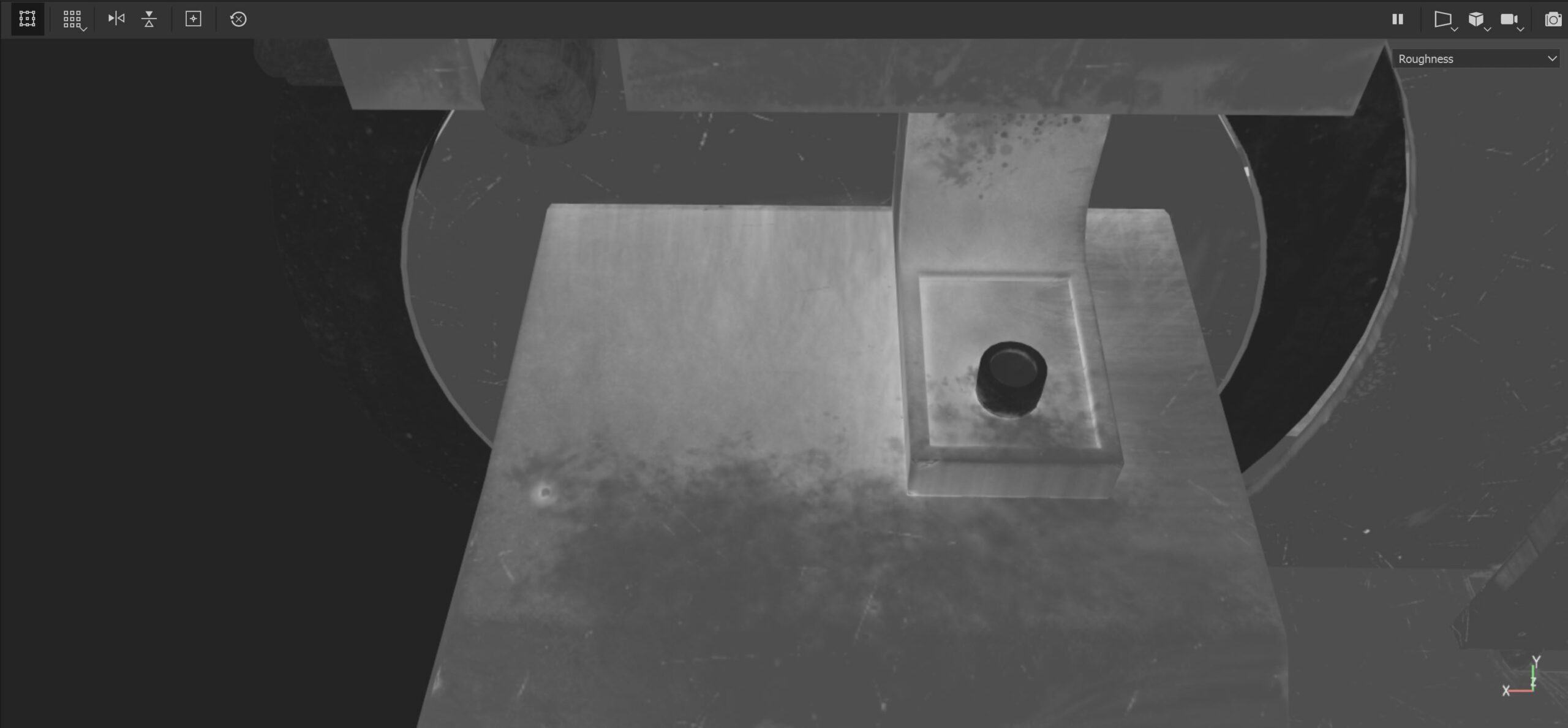
4. Capture the surface roughness
Remember that a roughness map describes both areas where reflections are more concentrated and defined and areas whose reflections appear blurred and dim, due to the scattering of the reflected light on uneven surfaces.
You can add more light sources in order to discover more roughness. I first set the camera and then I experimented with some additional lights, just to capture the reflections.
A word of advice: remember that the reflection is stronger and more visible when light hits the surface at a grazing angle and your point of view tends to align to the surface (Fresnel effect).
5. Create a 360° render to showcase your model
To check the quality of your materials and show your work, I suggest that you create a turntable version of your model, with a proper lighting setup.
You might discover areas where you have to tweak the roughness as well as other details and so a 360 render is what you need!
In my Artstation project page, I created a turntable render where you can see how reflections appear. Have a look!
Conclusions
This part brings us to the conclusion of this article.
We started talking about metals as conductors and we discovered their base properties.
We then tried to observe the slicer in order to reveal the details such as scratches, dirt and dust. While creating realistic PBR material, my advice is try to observe many references or imagine how your material would look like under certain circumstances (age, weather exposure, environment etc…).
In the third part we explained how to produce the previous effects and materials in Substance Painter, considering the power of the tool in terms of layers, masks, generators, filters and so on.
Finally, I gave you some tips for creating renders of your piece.
Those tips are software indipendent and so I encourage you to follow them when you showcase your 3D models.
My name is Francesco Furneri and I’m a 3D artist with more than 10 years experience in 3D Computer Graphics. I specialize in 3D Modeling and Texturing and have worked for 3D companies as a modeler, technical artist, and texturing expert. I also freelance in the States, creating organic 3D models of characters and prop textures. Check out my Artstation page, and feel free to contact me.