As you’ve now become more familiar with Yeti, it’s time to dig into a new hairstyle technique: 3D dreadlocks.
Hello everyone, and welcome back to this Yeti series. In our very first episode we learned the fundamentals of Yeti for Maya in which we produced a basic hairstyle for a cartoon character (Part I). We then moved on to more advanced topics involving the clumping, as a way of creating more variations to the hairstyle (Part 2). From there, we learned braiding techniques and the Yeti Graph Editor extensively to accomplish a realistic result (Part 3). In this fourth part, we’ll explore using the Yeti Graph Editor to model 3D dreadlocks.
Gathering References
When creating 3D dreadlocks, the first step is to find proper references. Since these hairstyles can vary from each other, we can collect pictures and choose the hairstyle we like the most.
The process of choosing different pictures might take some time. Once you have a precise idea, you can start modeling your dreadlocks with ease. Details make the difference, but dreadlocks have their primary shape in common, made from braiding or “locking” hair, which starts at the scalp and can hang in varying lengths. That suggests we can follow a common workflow for the main shape. We’ll get into the details afterwards.
The General Concept of 3D Dreadlock Creation in Yeti
Yeti is powerful, and gives you all the tools needed to model different hairstyles. That being said, this tutorial requires that you read part 1 and part 2 because some steps are taken for granted.
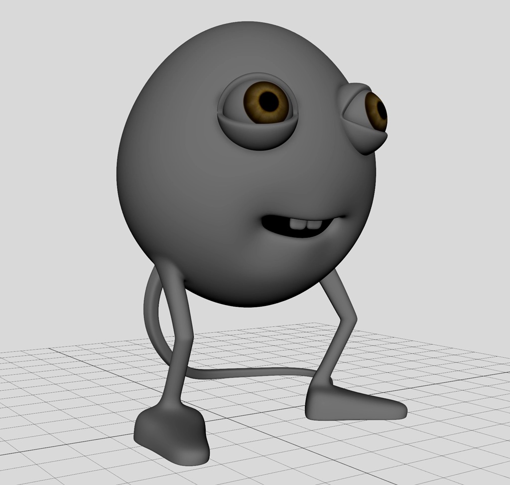
Using our character from the previous episodes, we want to create a singular 3D dreadlock from a very simple Yeti Groom node. This is the basic idea:
- We build a simple network where, from a single strand, we make a series of fibers grow.
- We convert those fibers into new strands and use them as input for our singular string.
- When we are fine with the main shape, we’ll continue adding further details.

Modeling the Shape of the Initial Strand
First, select the mesh and find the Yeti menu where you click on “Create Yeti Node on Mesh.” As described in part 1, this action creates a node (rename it “dreadlocks“) that we can use in the Yeti Graph Editor.
Again, select the mesh, and from the Yeti menu click on “Create Groom on Mesh“. This action creates a second node (call it “dreadlocks_groom“) and allows the Grooming Tool to be used on the character. From that interface, we can shape our strands which model our future fibers.
Open the Grooming Tool. Select add Tool with a small brush size, and add a single strand which will be the root for our string.
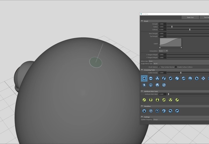
Add Tool with small radius 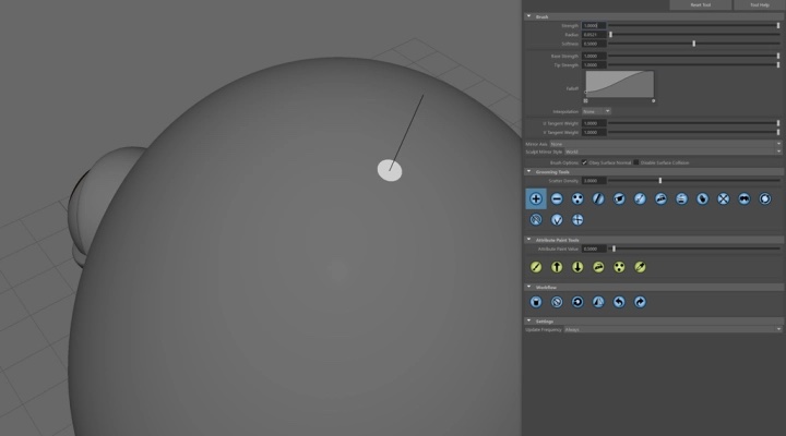
The single strand
You’ll have to change your strand length as we explained in part 1.
Once you have the correct set up, you can start using the Sculpt tool in combination with the Comb tool to give it a bit of shape.
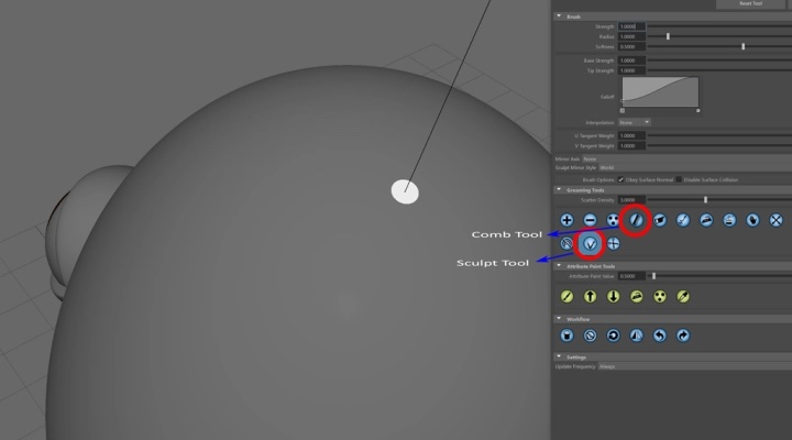
Selecting the Comb and Sculpt Tools 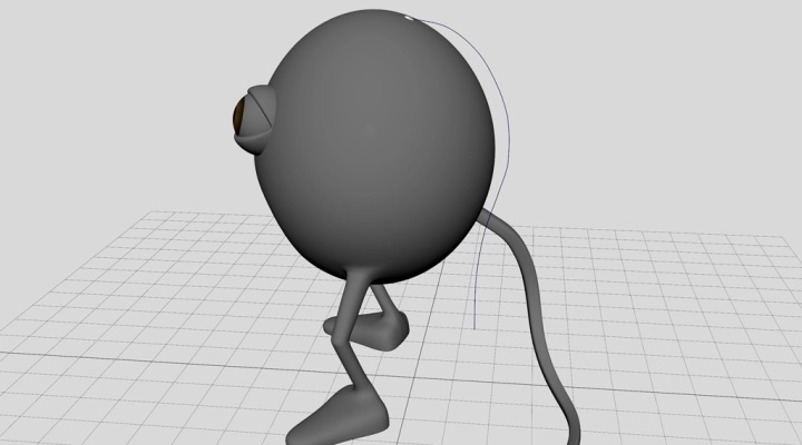
Shaping the strand
Building the Basic Yeti Graph
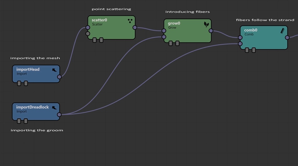
Same as our first set up, we now add nodes in order to grow fibers along the previous strand. Before working on the Yeti Graph, remember to add the groom shape to the input grooms tab in the main Yeti Node. Refer to part 1 to see this step in detail.
Until now, the process hasn’t been too fancy! We practically grew our fibers from the previous strand down to its length.
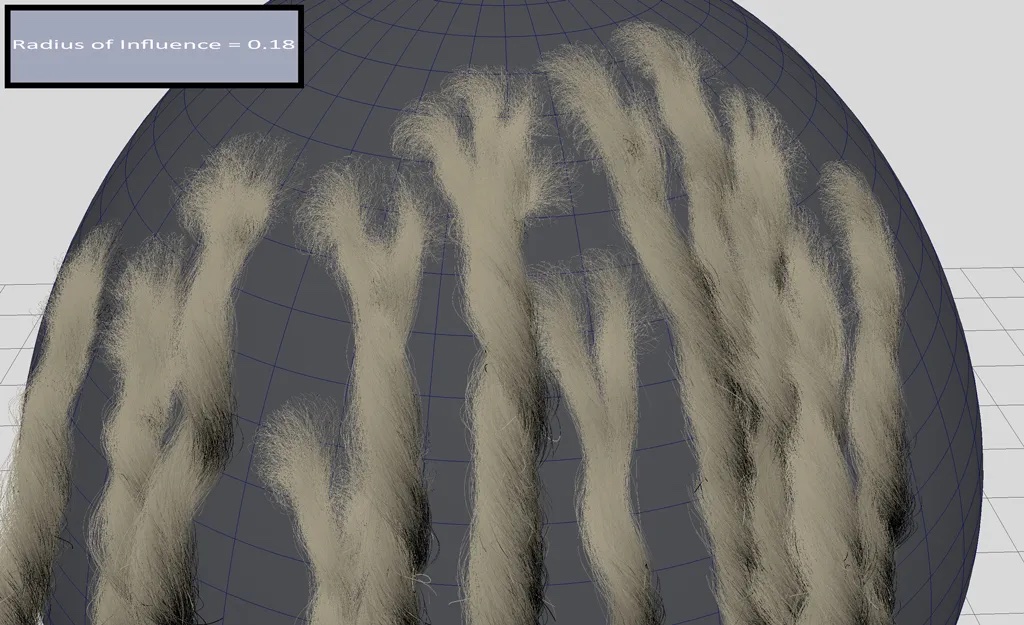
Note: Remember to set a low Radius of Influence in the initial “dreadlocks_groom” node to avoid fibers growing all over your mesh.
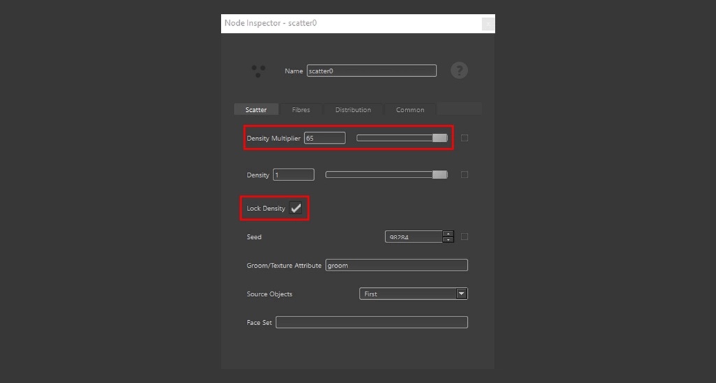
Scatter node settings 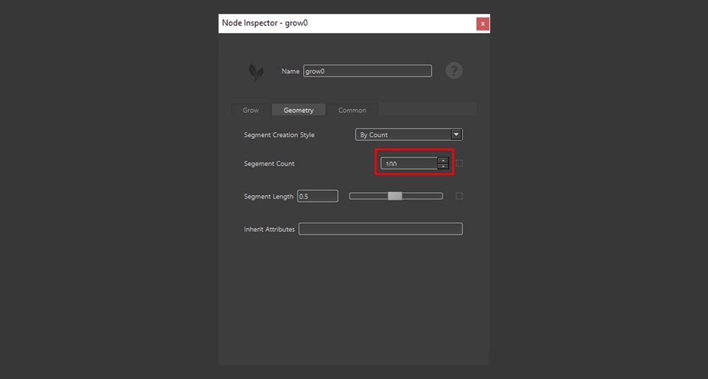
Grow node settings 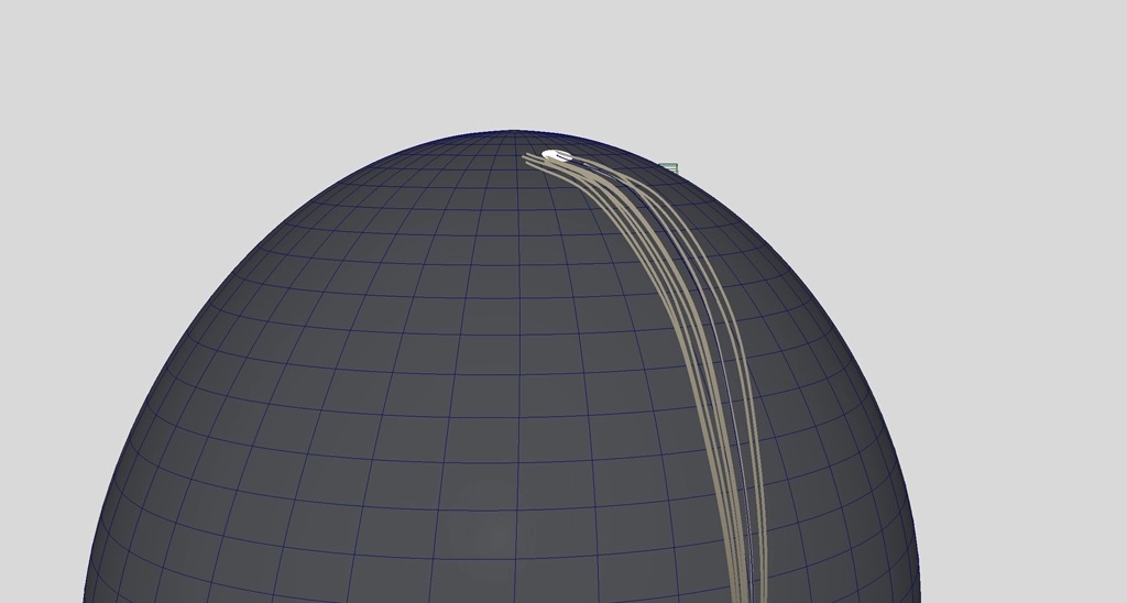
The result on the Comb node. Fibers following the strand.
Finalizing Fibers before Converting to Strands
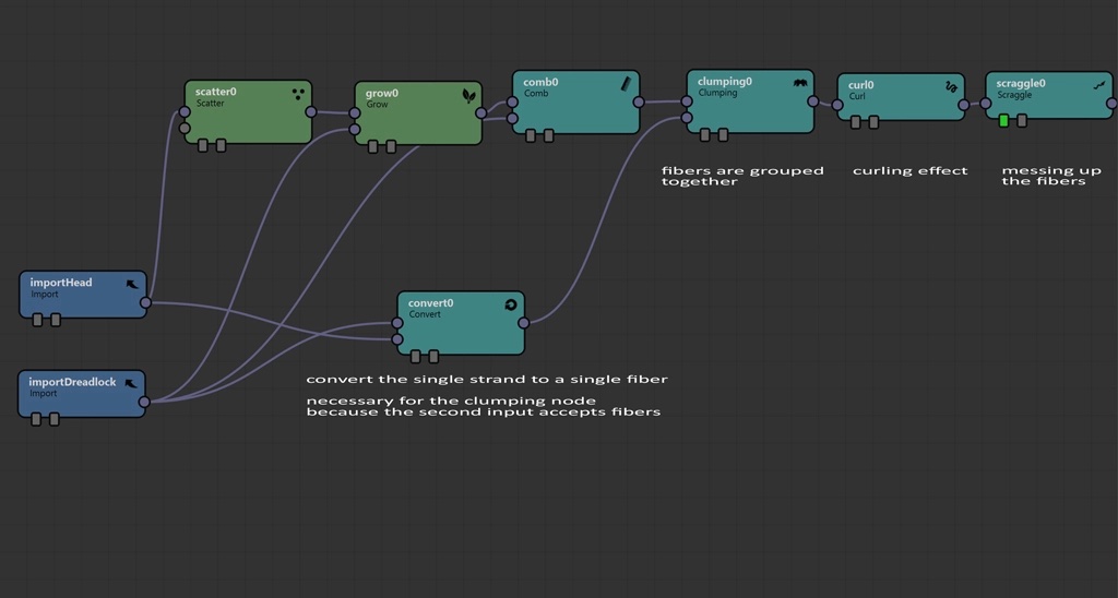
Our graph needs more nodes with the purpose to convert the result to strands. At the end, the following graph will serve as input for our final dreadlocks, which will follow a more natural direction.
The Convert node takes the initial sculpted strand and turns it into a fiber. This will be used as second input for the Clumping node. The Clumping node takes the fibers created from the previous network, and collapses them under the single fiber. Furthermore, the clumping node keeps the default settings.
Finally, we add a Curl and Scraggle nodes as modifiers. The following graph shows the single nodes.
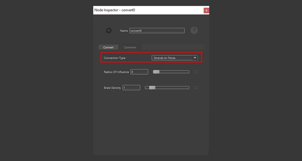
Convert node settings 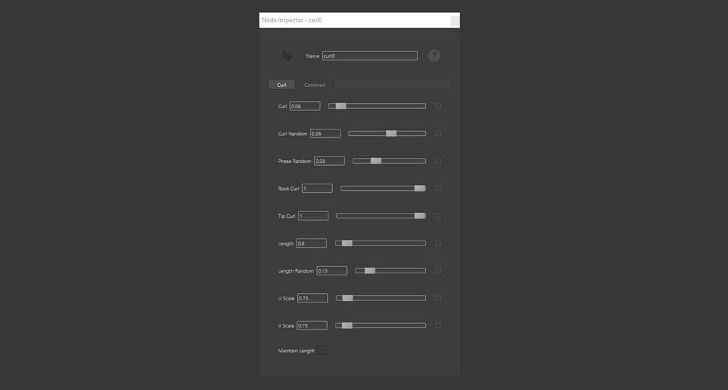
Curl node settings 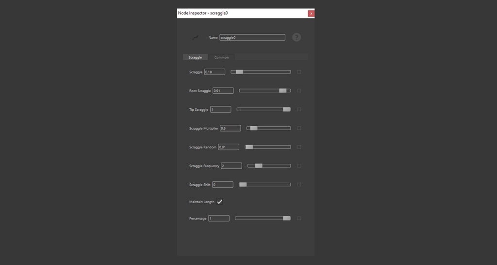
Scraggle node settings
Clumping node effect 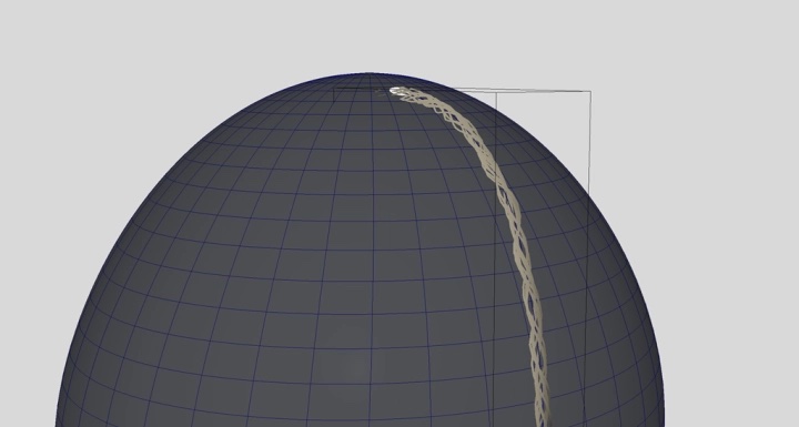
Curl node effect 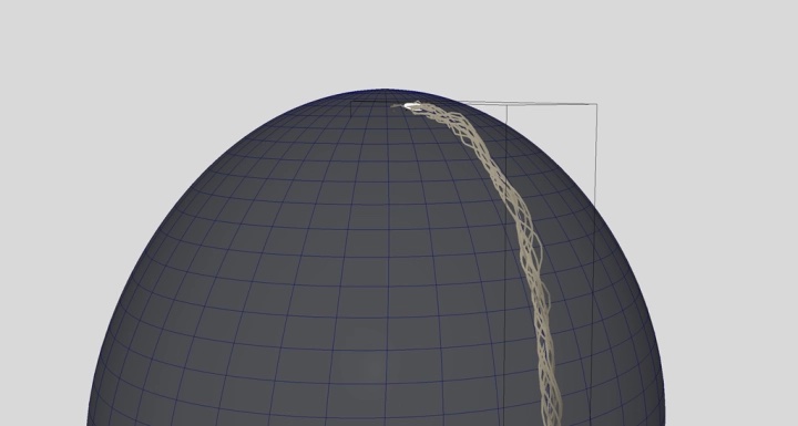
Scraggle node effect
Converting to Strands and Creating the Basic 3D Dreadlock
Now that we have fibers, we can convert them into strands and use them as input for our actual dreadlocks.
The idea is simple: the elements in the red rectangle use almost the same nodes from before. It’s just a matter of tuning the parameters to create something interesting.
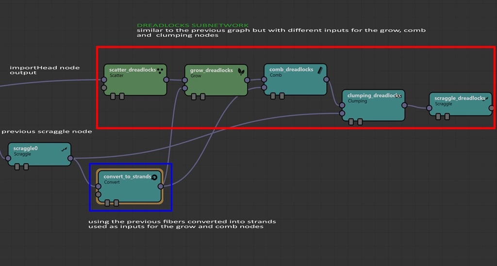
Note that the “convert_to_strands” node acts as input for both the Grow and Comb nodes. It models our final fiber shape.
I invite you experiment with some parameters, so the “scraggle_dreadlocks” node produces something interesting for your hair. Remember to add a Width node at the end to make the hairs more realistic.
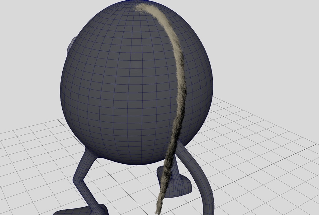
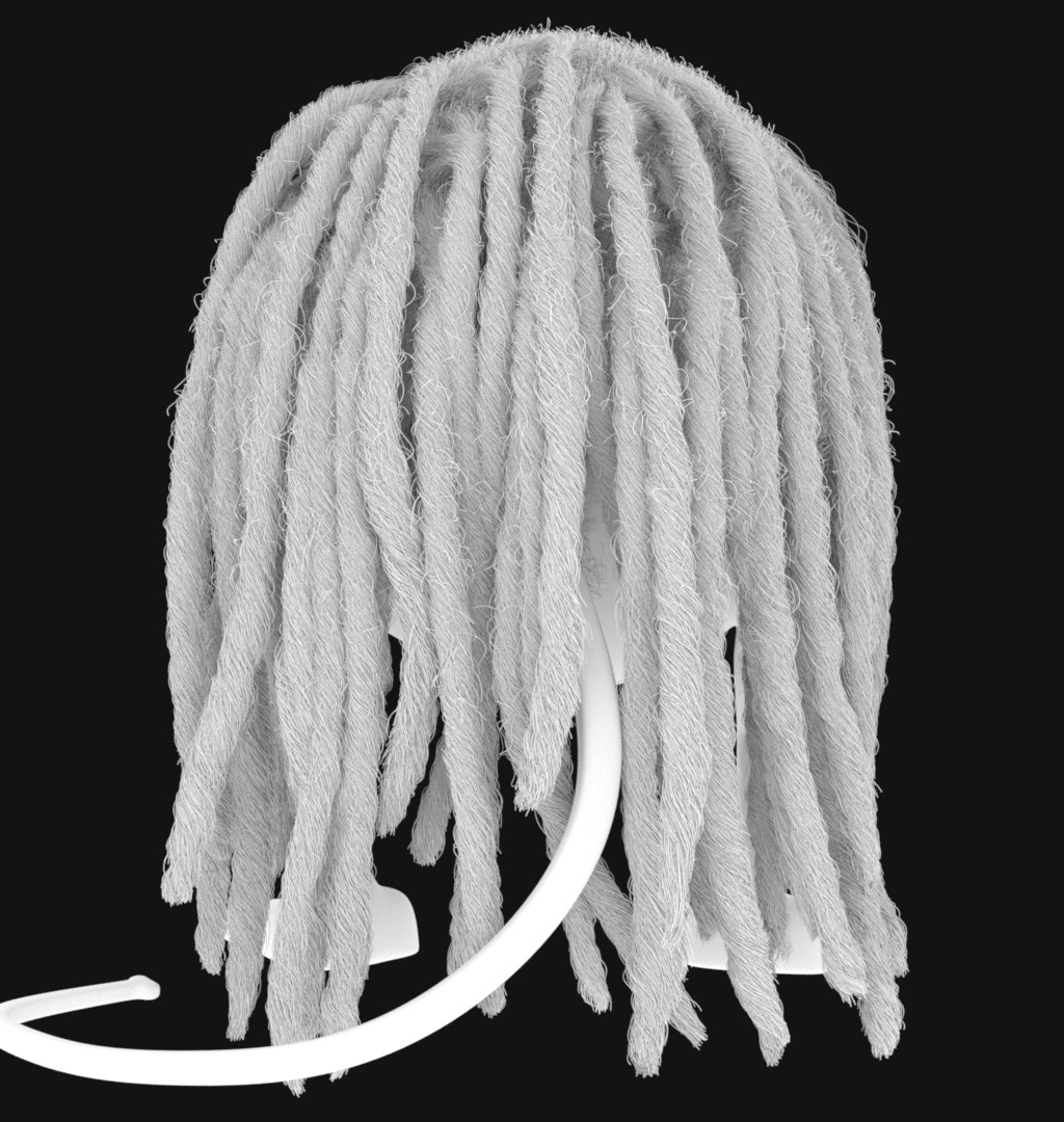
You should obtain something like this in the Maya viewport.
Next, we create multiple strands from our Grooming Tool. Remember that once the network is built, adding a new strand is an easy operation.
- Enable the option called “Conform New Strands” from the tab named “Strands” of our “dreadlocks_groom_node.”
- Use add Tool to add a new element.
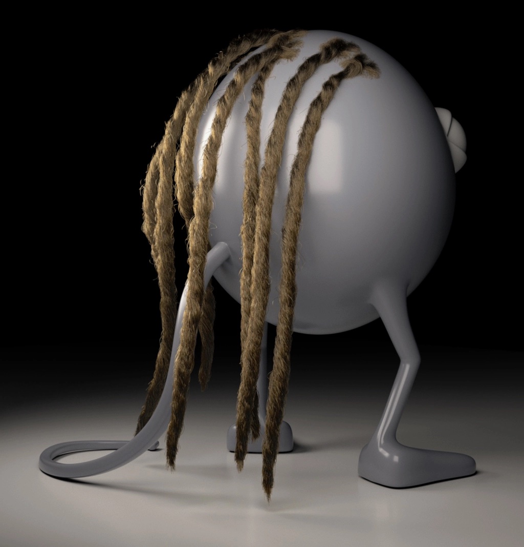
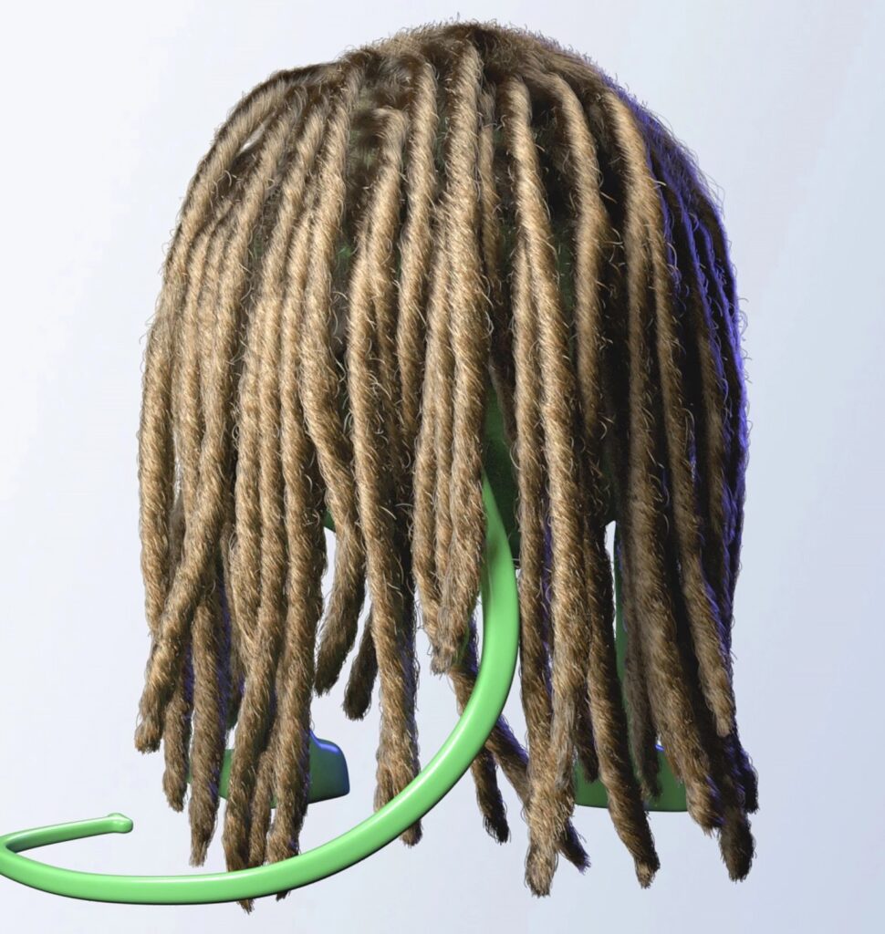
Adding shading causes the dreadlocks to look more interesting, but here are some observations to note:
- The root of our string is too thin compared to the rest.
- It’s better to avoid the curly effect close to the root.
- Always a good idea to add more details, like flyaways, because it happens in reality (the following render already has flyaways).
- We can add more variations to the string shapes and the tip, in order to make the result even more interesting
How to Thicken the Root
There are different ways to thicken the root.
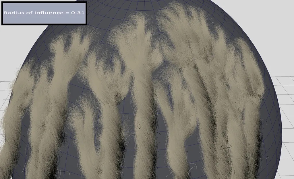
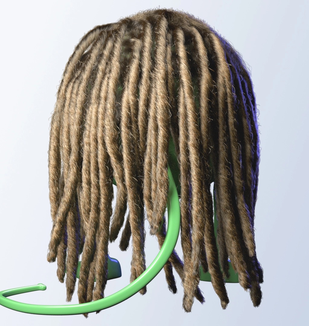
The easiest way is to increase the Radius of Influence of the “dreadlocks_groom.” The result of this action is to grow more fibers clumping into the related rope from the root. Imagine that more fibers at the root are needed to create that dreadlocks style. After different tests, a value between 0.25 and 0.3 might work in my case, but you can try other values.
The result is much better in the following image, but you can always tweak that value since you are using a procedural network.
Controlling the Curling Effect
The effect of the Curl node should be applied a bit distant from the root. We don’t want the root to be affected by the Curl node. For this task like this we use curve expression. This method performs a parameter interpolation between values.
In our particular case, we want to interpolate from a value of 0 (at the root) to a value of 0.08 (a bit distant from the root). The last value is being maintained towards to tip.
Our expression:
curve(param, pos0, val0, interp0, pos1, val1, interp1);
- param: we use a common variable $strandu which describes the position along each fiber, where 0 means root and 1 means tip. Along the fibers we have values between 0 and 1.
- pos0: the first position to consider along the fibers.
- val0: the value applied to position pos0.
- interp0: the interpolation function at pos0 (3 means a cubic function).
- pos1: the final position to consider along the fibers.
- val1: the value applied to position pos1.
- interp1: the interpolation function at pos1 (3 means a cubic function).
This is our current function:
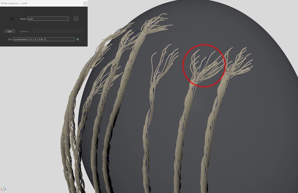
curve(strandu, 0, 0, 3, 0.1, 0.08, 3);
We add this function to the Curl parameter of the Curl0 node. This tells Yeti to activate the curling effect from a distance equal to 0.08 from the root of each fiber.
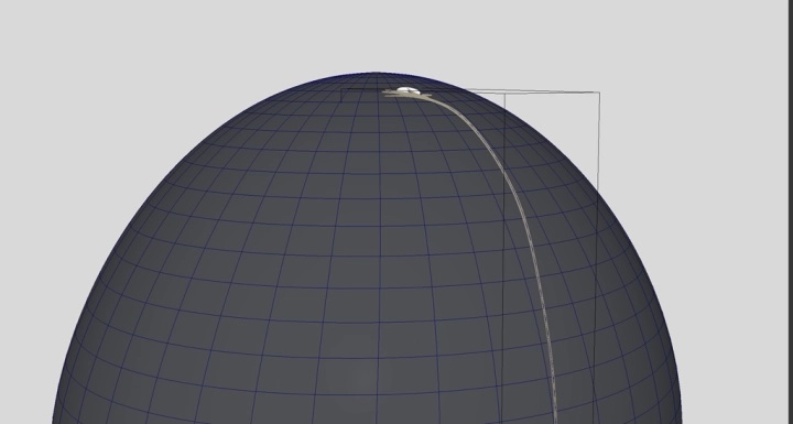
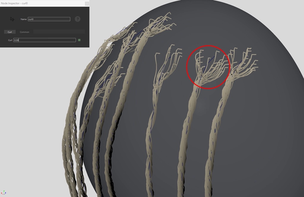
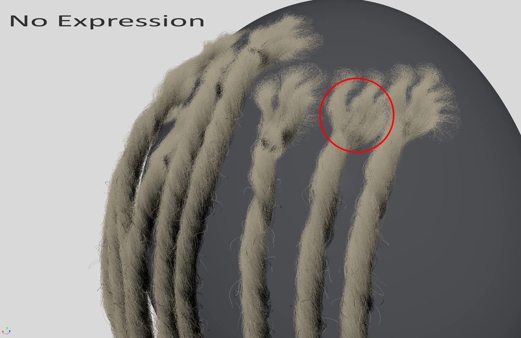
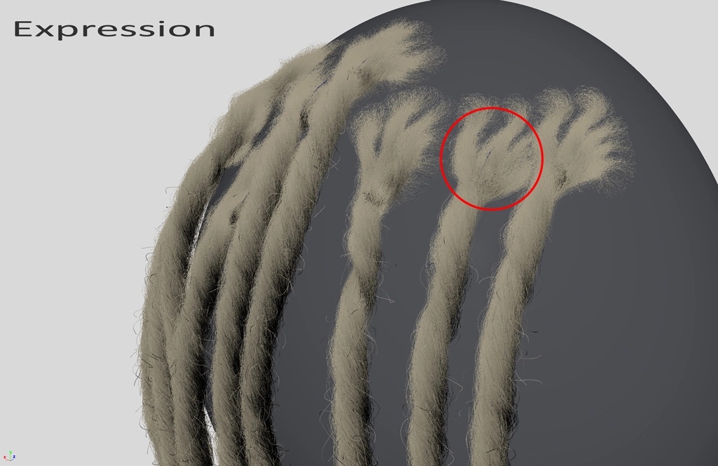
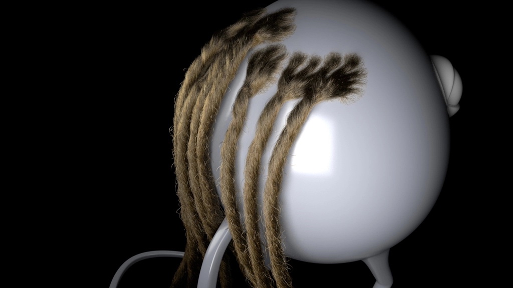
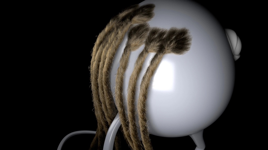
The following figure shows the curl0 node result with and without the aforementioned expression. See how the curling effect starts just after the root.
Flyaways
When you look at some references you’ll notice the presence of flyaways throughout the dreadlocks. They are randomly spread and oriented in different directions.
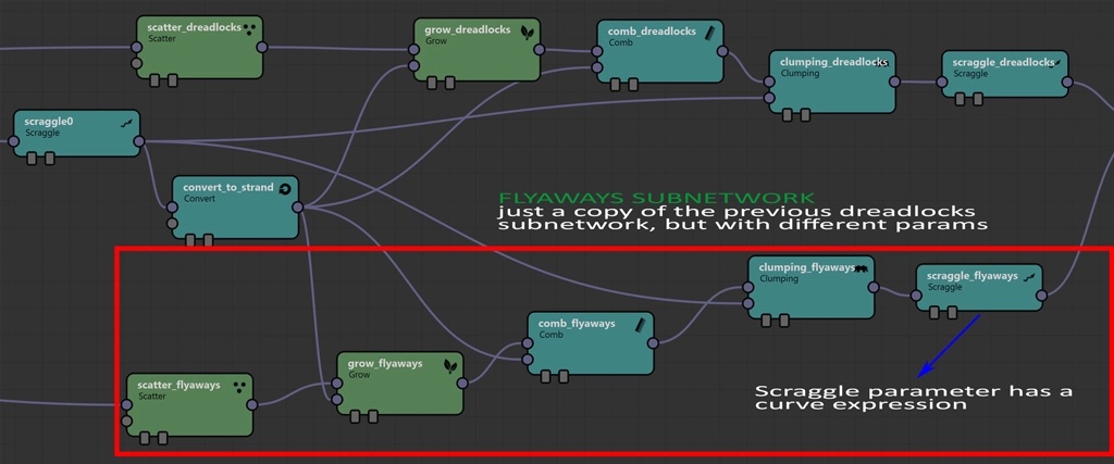
Using a similar approach from the braid episode, let’s create a sub layer consisting of small, random hairs popping up. We will duplicate the dreadlocks subnetwork and change some parameters to create a thinner shape than before. From there, add an expression to the Scraggle parameter of the scraggle_flyaways node.
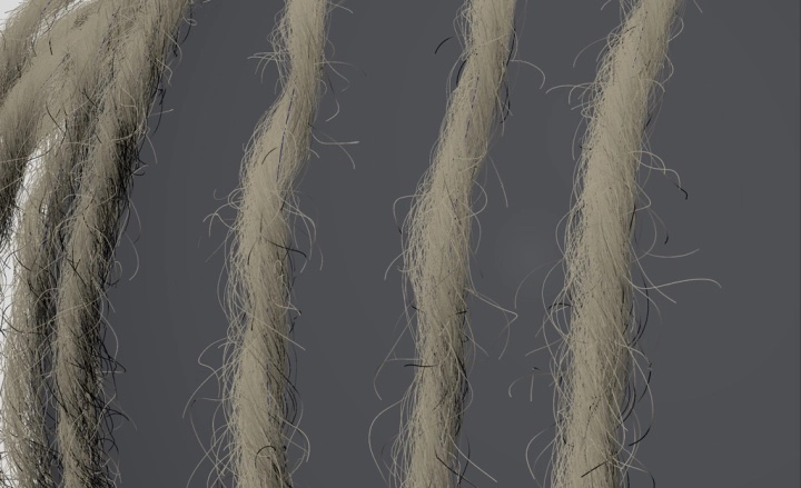
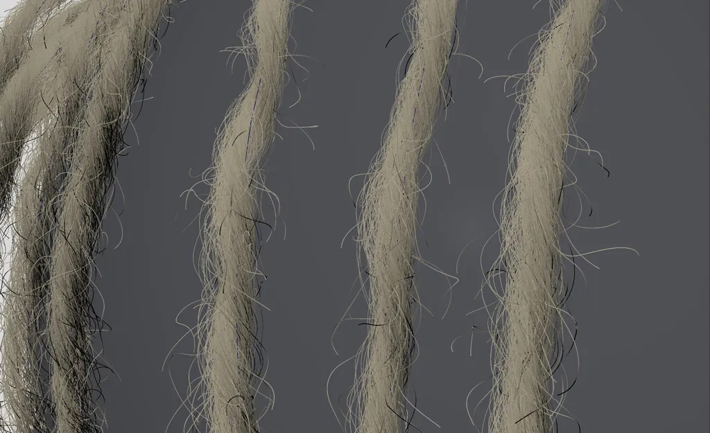
On the left side, the result of our flyaways subnetwork, on the right our dreadlocks subnetwork with no flyaways. In this case, again, I let you experiment with the parameters to obtain something similar to this.
Flyaways subnetwork 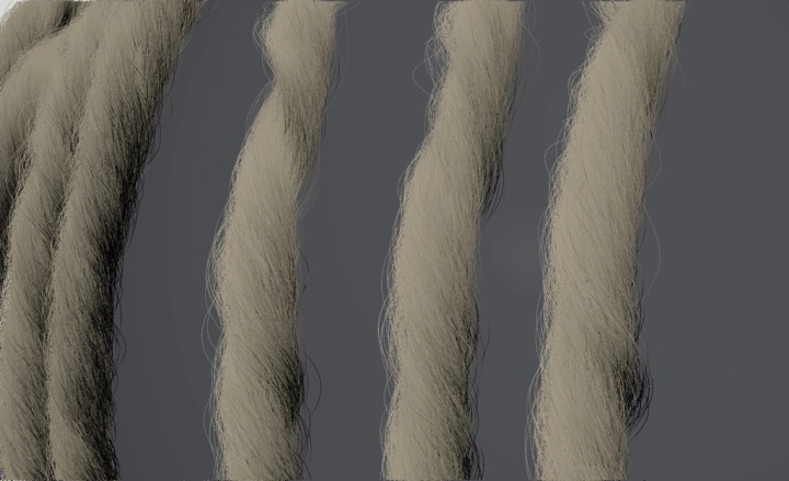
3D Dreadlocks subnetwork
The expression we used in the scraggle_flyaways node is very similar to the previous one.
curve(strandu,0.8,0,3,1,1,3);
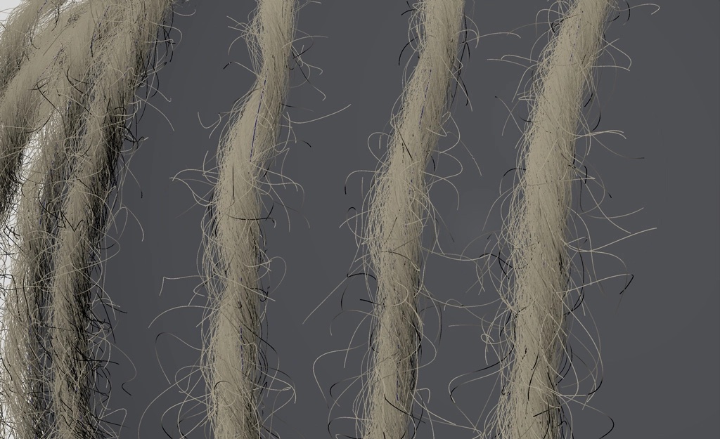
This time, we apply the scraggle effect to the tips only. We remove the effect until the length is 0.8 (referred to each fiber), and then we scraggle towards the tip. Alternatively, you can multiply the expression by a float number to set the scraggle intensity. In the next example, I intentionally use an extreme multiplier to show the difference.
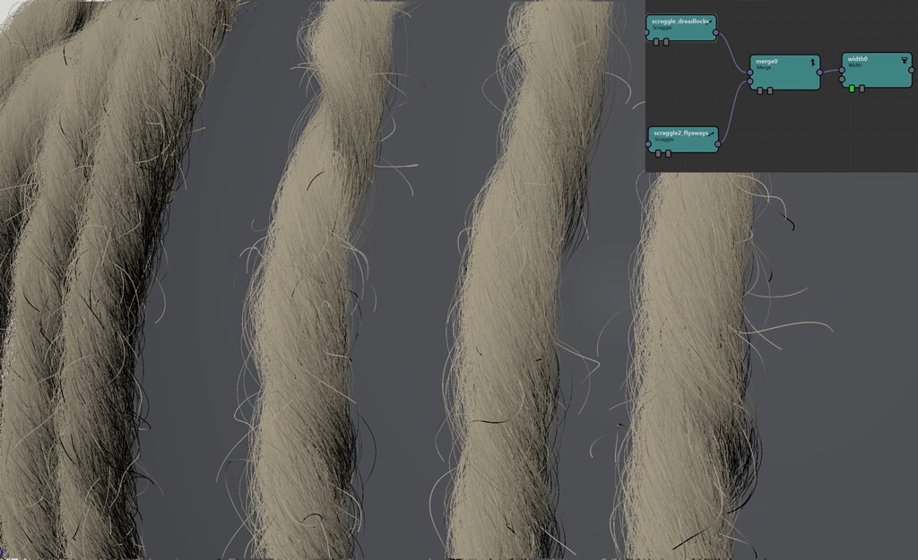
As final step, let’s use a Merge node to combine the two subnetworks.
Controlling the Hair Clumps at the Root
If you look at the root, there are big clumps. We want to make them smaller with a smoother effect.
We can decrease the clump size by applying the already known expression to the Weight parameter of the clumping_dreadlocks node.
There are many ways to adjust these details. As you probably noticed, expressions are very useful. By tweaking values, you can refine small parts that are impossible to adjust by hand.
In our dreadlocks subnetwork, consider the node called “clumping_dreadlocks” and in the Weight parameter use a curve expression like this:
curve(strandu, 0, 0.33, 3, 0.24, 1,3);
As you can see, we reduced the clumping effect at the root.
Adding Imperfections to 3D Dreadlocks
Our dreadlocks are almost complete, but we still need some adjustments to make them look more natural.
We can add a new expression to specific entries of our Curl node. In particular, the parameters U Scale and V Scale are responsible for scaling the shape of the curl effect.
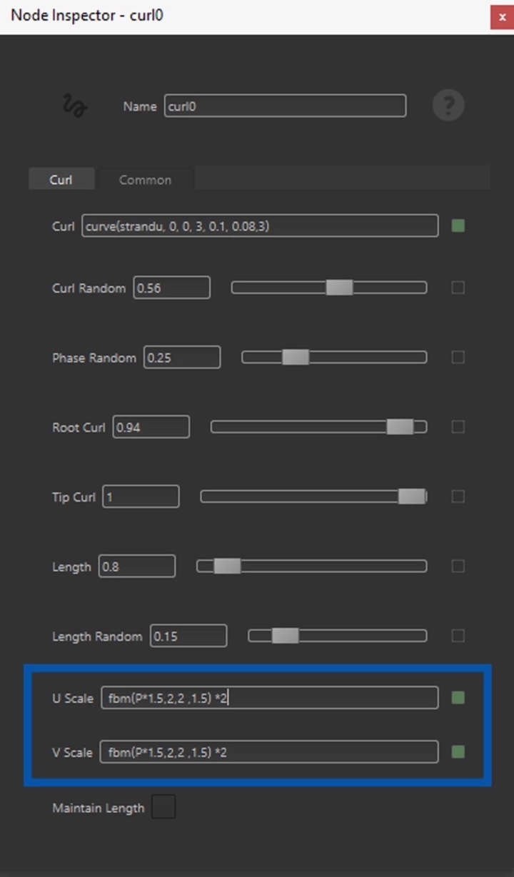
However, it’s better to use an expression to control the shape. The fbm expression is a multi-frequency noise function:
fbm(P * 1.5 , 2, 2 ,1.5) *2
The first parameter considers the different points (vertices) along the fibers and is being multiplied by 1.5 to increase the noise frequency. The second parameter controls the octaves which are the levels of details you want the noise to have. The third parameter is lacunarity which represents how much detail is added at each octave. Finally, the fourth is a gain factor for the frequencies. Everything is multiplied by 2 to increase the global intensity of the effect.
The function might look a bit cryptic, but I recommend testing a few values to see the effect on your dreadlocks.
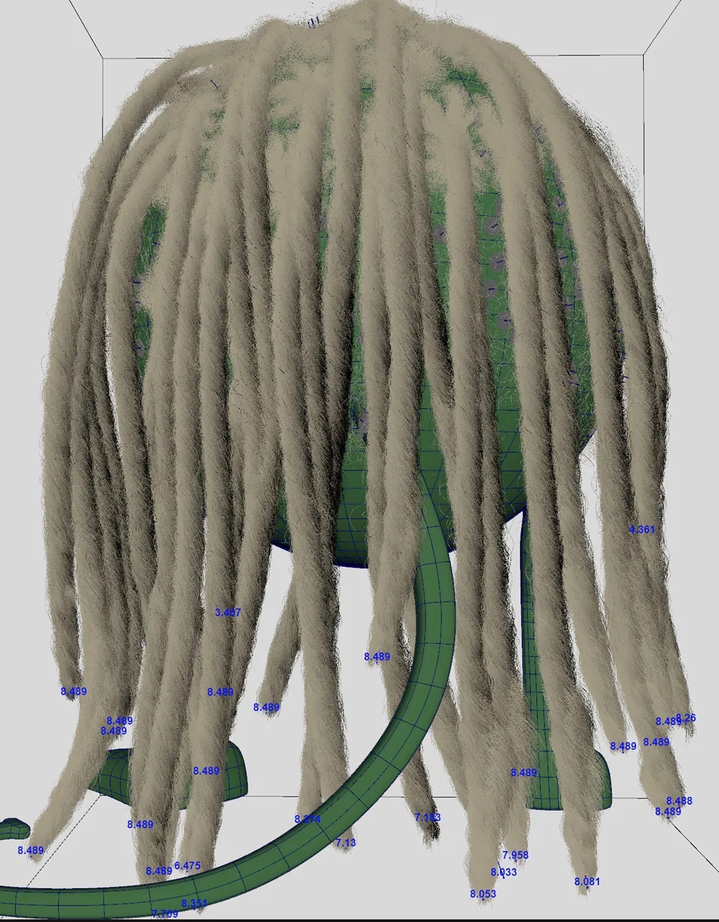

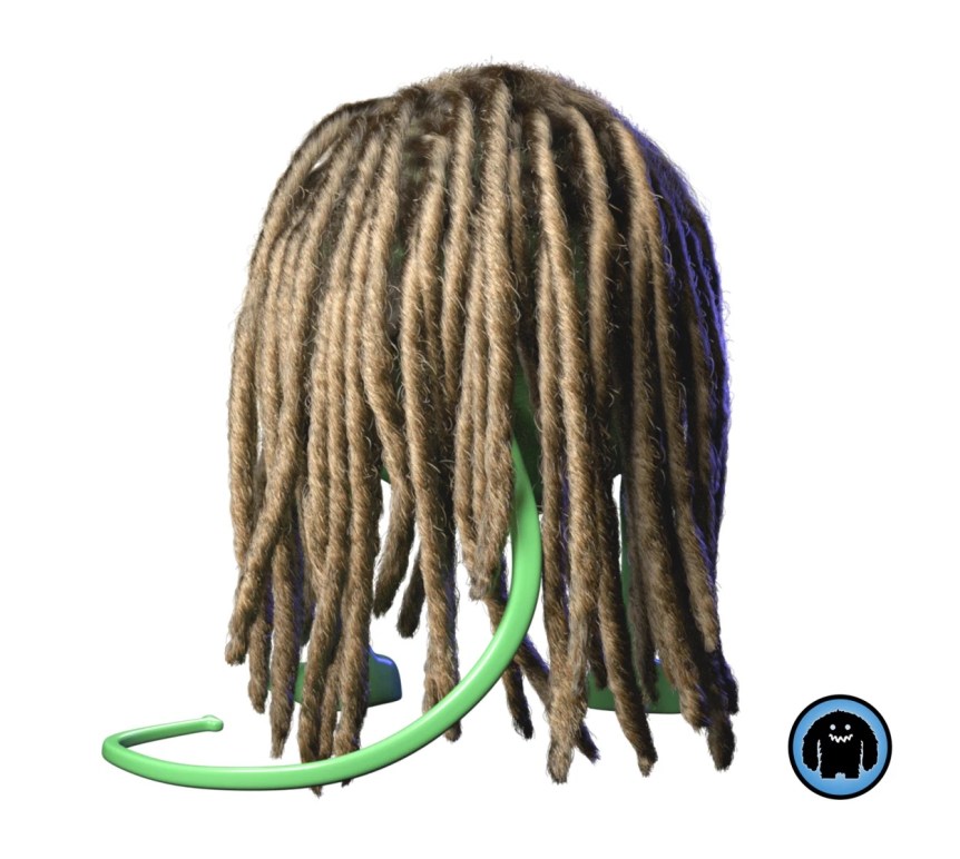
Rendering
Conclusion
In this Yeti episode, we witnessed a robust method for creating 3D dreadlocks inside of Maya.
As a first step, we started from a simple strand and created some fibers. We then applied different effects such as the curl and scraggle nodes to create a realistic result.
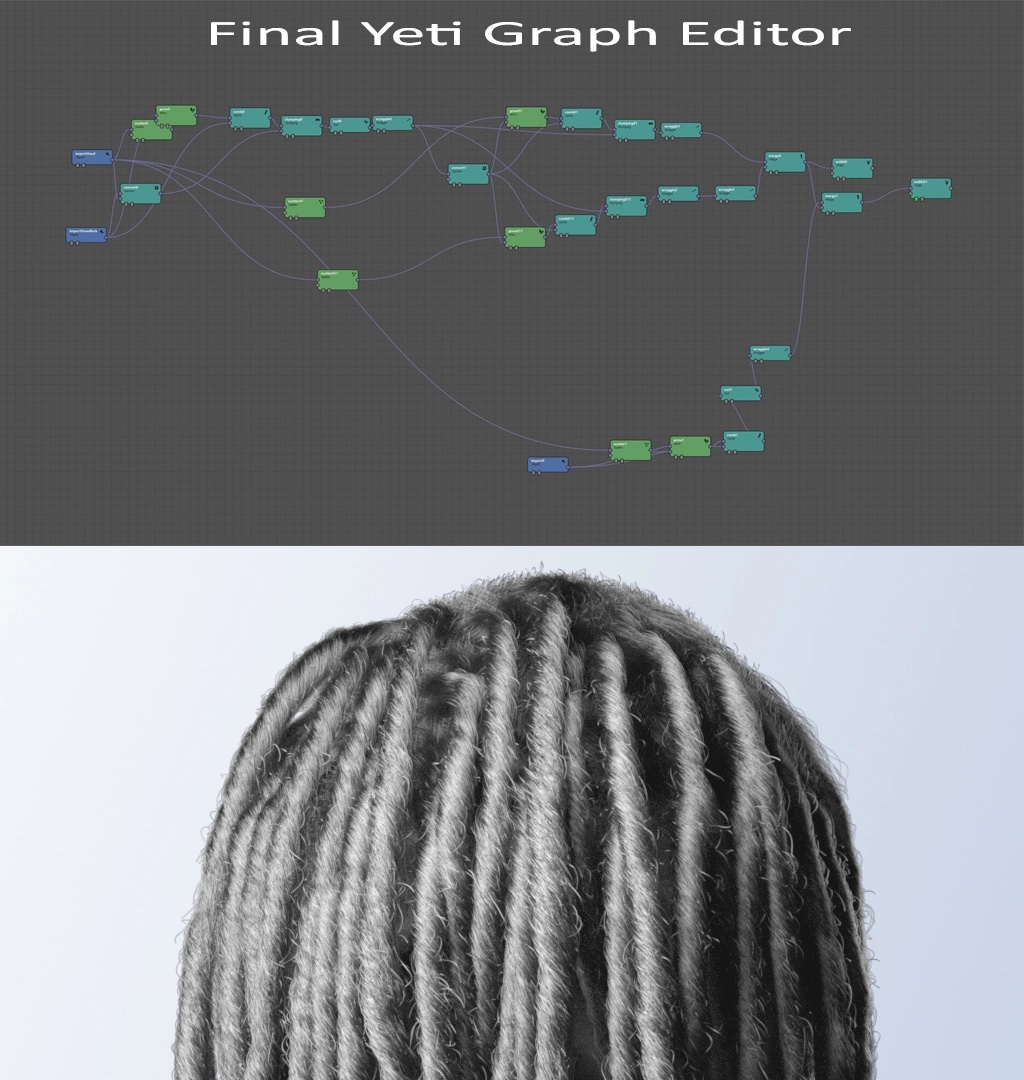
We added flyaways by duplicating part of the existing network. The final Yeti Graph Editor also contains a second grooming node for very short hair underneath that I added to cover part of the head. This section wasn’t covered, so I’ll leave it as an optional exercise to you.
If you liked this article, follow me at my LinkedIn where you’ll find some other interesting projects.
Building your own 3D character but don’t want to start from scratch? Check out the TurboSquid library for high quality assets.