Falloff maps are an extremely powerful tool for artists to utilize when creating procedural shaders. They are essential when trying to create any realistic shader that is reflective or has color changing properties like chrome, metals, and pearlescent paint. In order to use Falloff maps effectively, it is important to understand how the map works.
In this week’s edition of Turbo Tips, we’ll explain the ins and outs of Falloff map parameters. For our purposes, we are demonstrating with 3ds Max, but the ideas and concepts can be used in many other 3D programs.
Setting Colors
The first editable parameter is the map colors. Both of these colors will be actively blended using the Falloff type selected for the map. Texture maps or other maps can be used in place of colors, as well. For these examples below, the Falloff is placed in the diffuse slot. The default colors are black (0,0,0) and white (255, 255, 255).
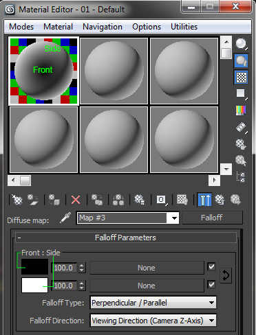
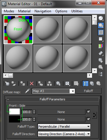
The name of the group at the top of this is rollout. This name changes depending on the falloff type selected (which is covered below). In all cases, the name on the left refers to the top color parameter, and the name on the right refers to the bottom color parameter. In the case of Perpendicular/Parallel, black is the front color and white is the side color. Colors can easily be inverted by clicking the arrow button on the right side. Viewing the material node, it is easy to see how the colors react for the type of falloff you are using.
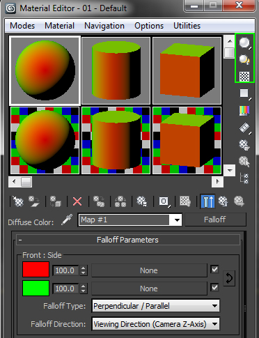
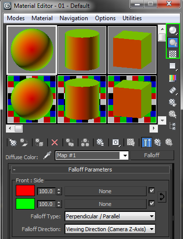
QUICK TIP: When editing your material, it is a good idea to have the material node viewable. After setting the colors, swap them back and forth to make sure the colors are on the correct surface. You can switch the sample type between a Sphere, Cylinder, and Cube sample, as well. It’s a quick way to view how your shader will look at different angles, and shapes in your model before having to do a full render.
You can toggle the node backlight, on and off, to view it with or without multiple light sources. When working with Reflections and/or Refractions, turn on the node Background to see how much the surface will be affected by your settings. Testing your shader this way can save significant amounts of time while developing shaders (as opposed to rendering your entire model).
Choosing the Right Falloff Type
There are five different types of Falloffs that can be used. It is very important to know how each one reacts so you can choose the correct one for your intended purpose. For these examples, all settings on the Falloff map have been left at default, except for changing the type.
Perpendicular/Parallel
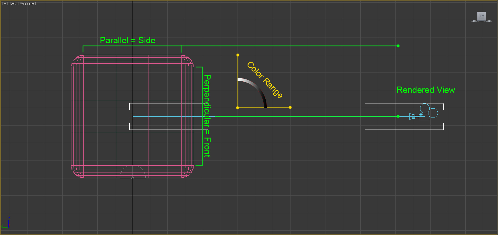
This is the default Falloff type. The falloff range is based on a 90-degree change in normal direction from face to face. Front faces are facing flat towards the view that is rendered. The Side faces are any faces that are 90 degrees from the Front face. The color range would be any face at an angle between the Front and Side faces.
Towards/Away
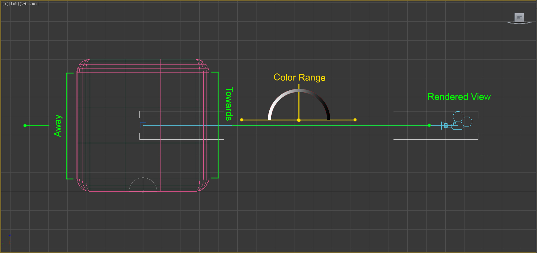
The falloff range is based on a 180-degree change in normal direction from face to face. Towards faces are facing flat to the view rendered. Away faces would be facing the opposite direction, 180 degrees, or back facing. The color range would be any face at an angle between the Towards and Away faces. This is a much wider range than Perpendicular/Parallel. You would never see the set Away color, only the color range from it towards the front of the view that is rendered.
Fresnel
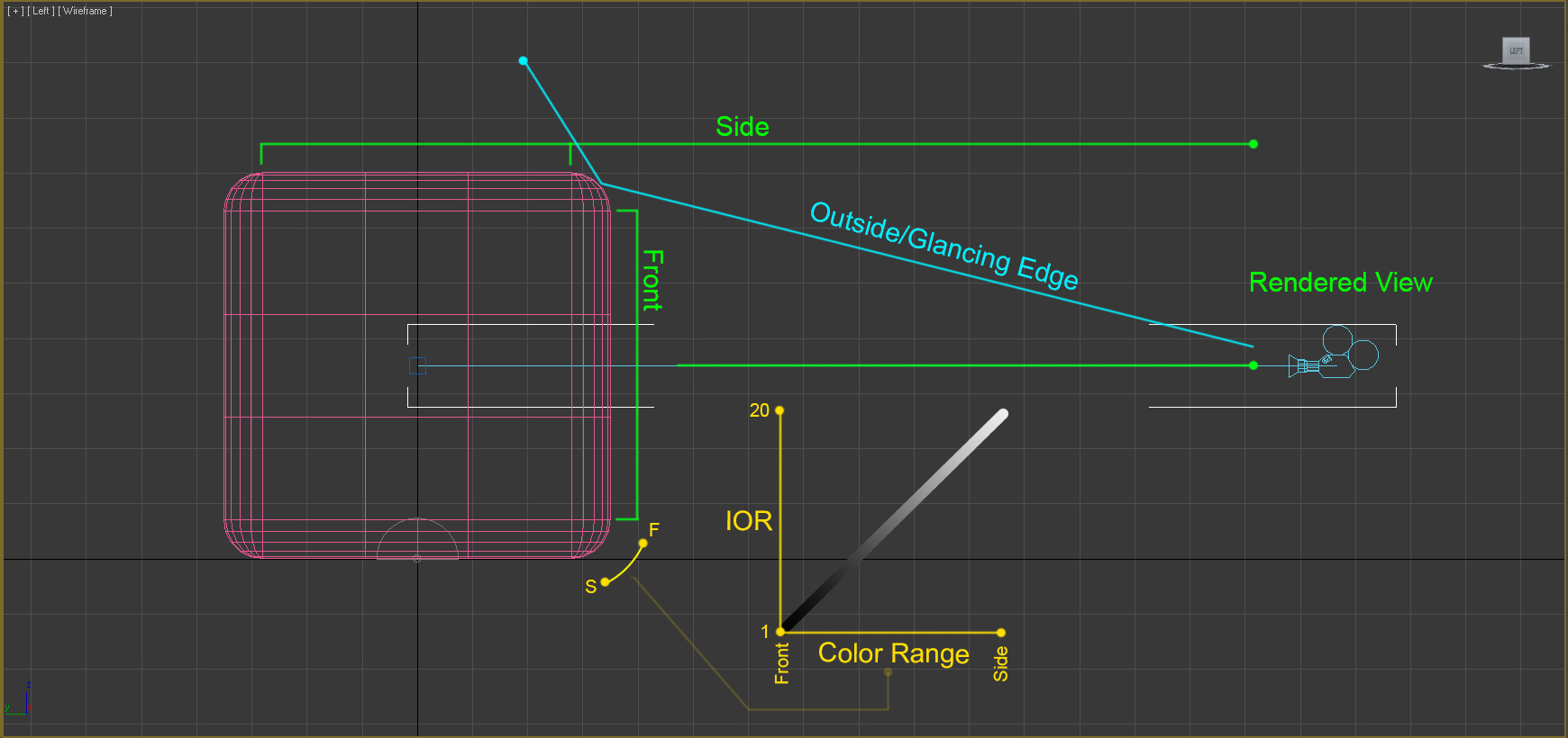
The falloff range is based on adjustments to the Index of Refraction (IOR). Front faces are facing flat to the view that is rendered. Any faces 90 degrees from the Front face are the Side faces. This type may seem similar to Perpendicular/Parallel, except the color range is much tighter, pushing the Side color to angled faces just visible from being flat to the view rendered. The color range is on a curve controlled by the IOR. Setting the IOR to 1.0 shows only the Front color. The glancing edges visible to the rendered view will be 100% side color above 1.0 value. As the IOR value increases, more of the Side color will be visibly blended with the Front color, until you reach the maximum 20.0 value. At maximum value, the Front color will match the Side color. This is easily viewable while looking at the material node.
This type of fall off is primarily used in the Reflection slot. At default values, it results in dim reflections on surfaces facing the view, with much brighter reflections on angled faces, creating highlights like those on the sides of a glass. VrayMTL has a Fresnel reflections box, which, when checked on, calculates the Reflection as a Fresnel type Falloff map being applied. The Front color defaults to black. If you want a different Front color, you will need to apply an actual Falloff map to the Reflection slot. The Reflect color you set becomes the Side color. The Fresnel IOR value by default is locked at 1.6 but can be unlocked for adjustments.
Shadow/Light
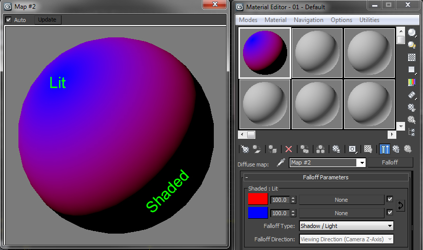
The falloff range is light dependent. Any faces in shadow will be the Shaded color. Any face in light will be the Lit color.
Distance Blend
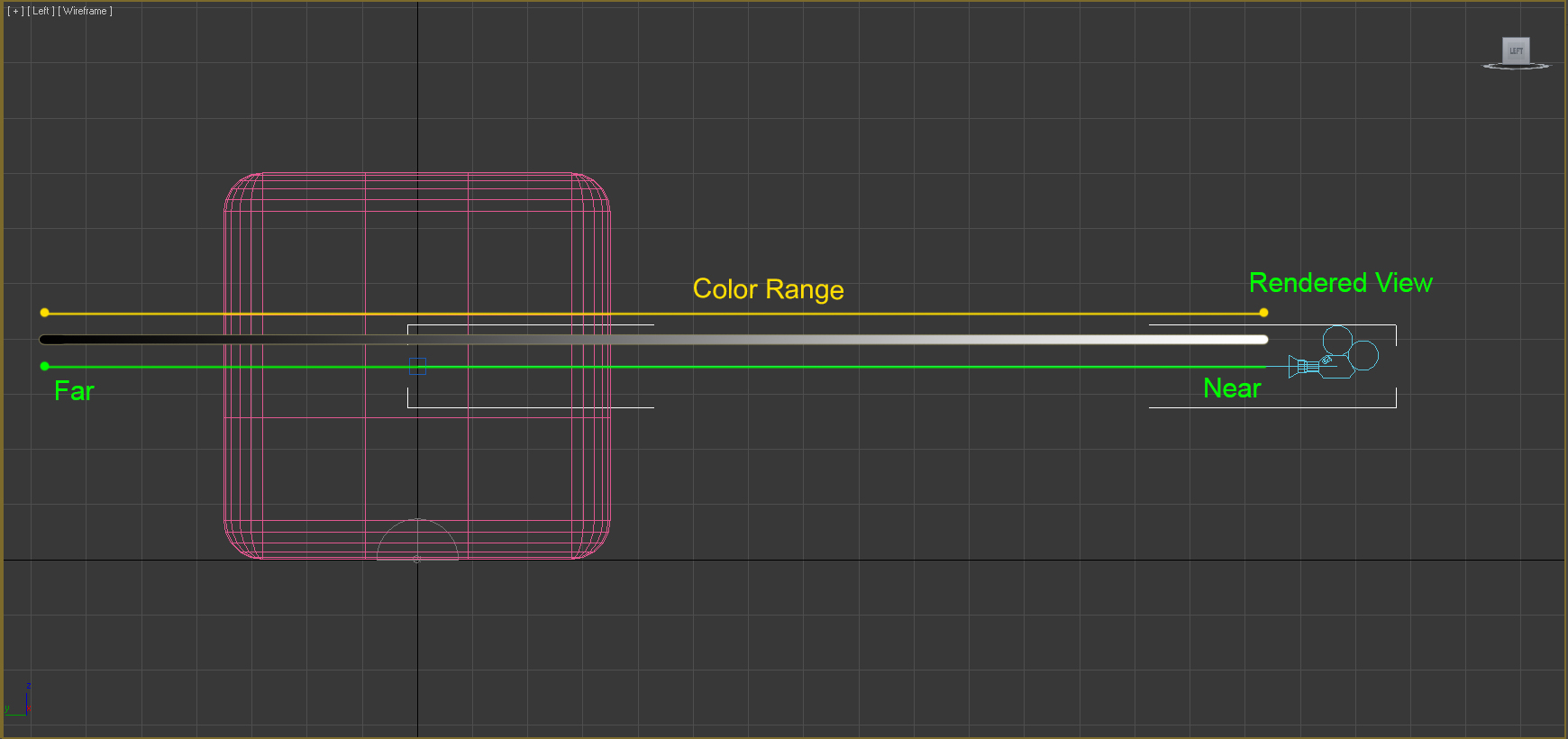
The falloff range is based on the distance specified from the camera, functioning like clipping distance. Color range affects any face in between the two distances. Example uses include: reducing aliasing on large terrain objects or controlling the shading in non-photorealistic environments.
Falloff Direction
There are five direction options to choose from, in order to achieve the desired outcome. The default is usually correct for most material types, but there may be situations where you would want to change the falloff direction.
Viewing Direction (Camera Z-Axis)
This sets the falloff direction relative to the camera (or screen). From the rendered view, the color range runs from front to back. Changing object orientation doesn’t affect the falloff map. This map is the default. (See below for example.)
Camera X/Y Axis
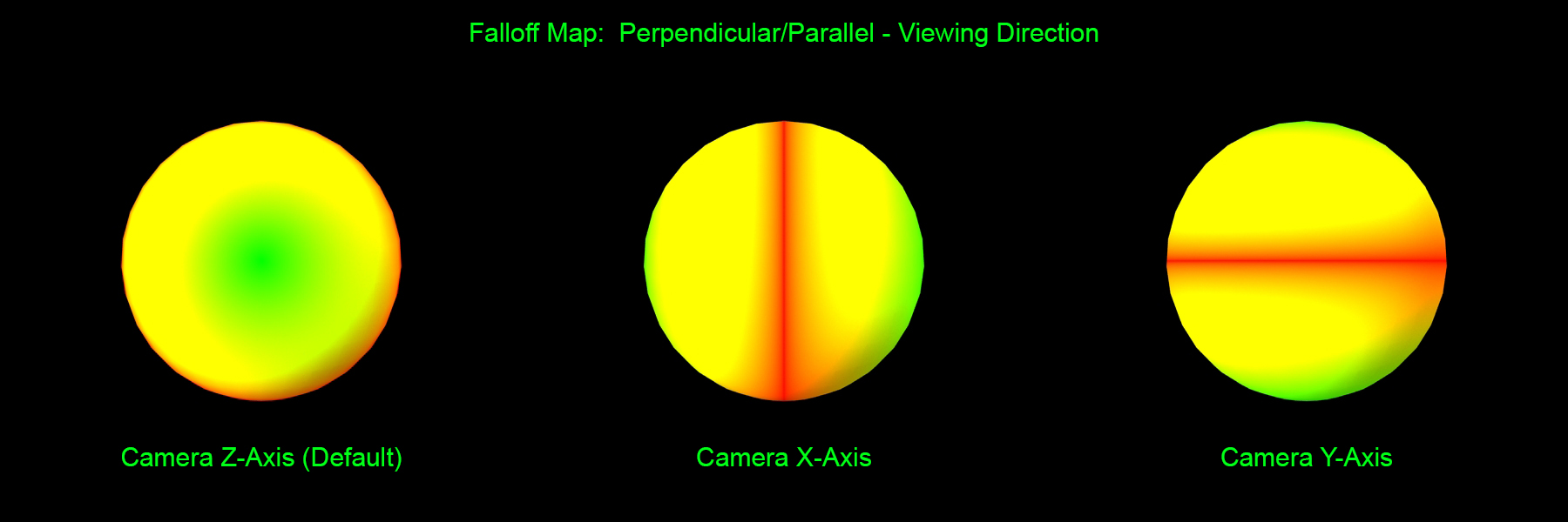
Similar to the Viewing Direction, except using Camera X-Axis changes the color range from left to right of the rendered view. Camera Y-Axis changes to color range from top to bottom of the rendered view.
Object
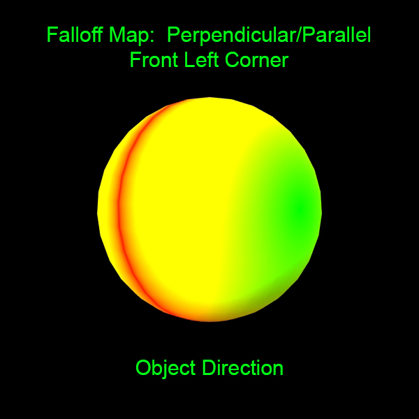
Pick an object whose orientation determines the falloff direction. Click Pick, and then pick an object in the scene. The color range is from the selected object’s center, moving away from it.
Local X/Y/Z Axis
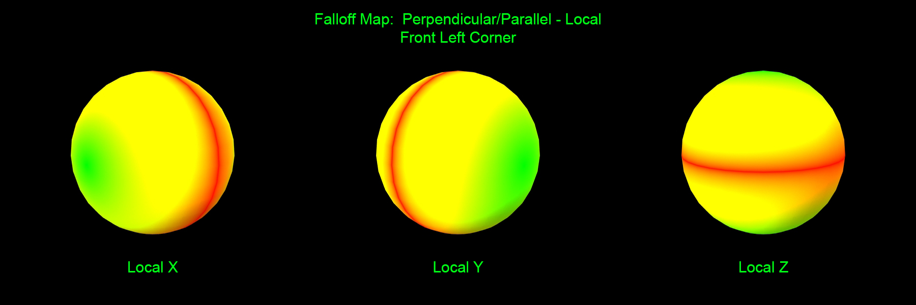
This works the same as Object direction, except you set which axis of the object the color range follows. Changing the orientation of the object changes the falloff direction.
World X/Y/Z Axis
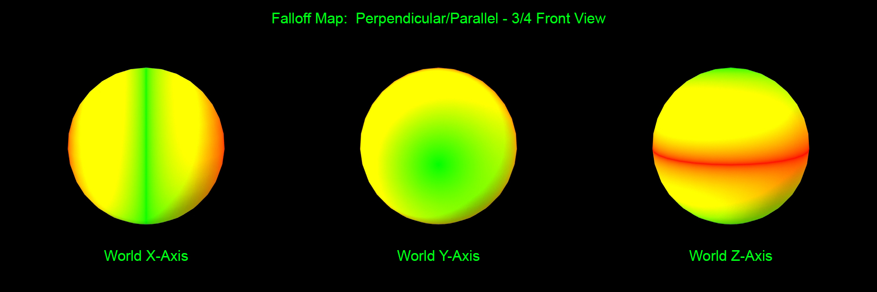
This sets the falloff direction to the world coordinate system axes. Color range will follow the world X, Y, and Z axis. Changing object orientation doesn’t affect the falloff map.
Mix Curve
Manipulation of the mix curves gives you direct control over the color range. You can alter how quickly the color shifts between the two options, for how long, and how many times.
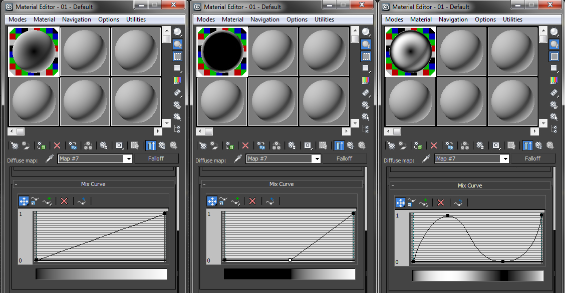
As you manipulate the curve, the gradient bar underneath the curve indicates how it affects the color range. This is more reliable to view than looking at the node, as your falloff may not be in the diffuse slot as it is in the examples.
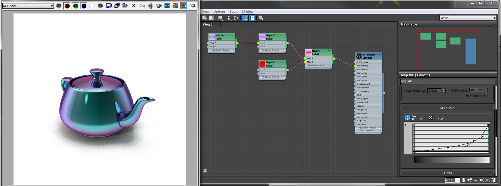
Usually, no alteration is needed for the mix curve for common material types. However, it can come in handy when making more difficult materials, especially color shifting surfaces such as iridescence, metallics, and pearlescents.
—
Calvin Bryson is the Senior Technical Artist at TurboSquid, and a 3ds Max expert. If there are any topics you’d like to see in a future edition of TurboTips, let us know in the comments below, or Tweet your question to @TurboSquid with hashtag #TurboTips.