Part of creating good topology for CheckMate Pro v2 subdividable models is to avoid T-vertices, the convergence of edges in a T formation, unless they are absolutely necessary for the flow of the model’s shape. T-vertices, or T-verts for short, when used incorrectly, will halt edge flow and cause poor subdivision.
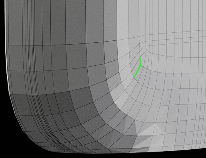
Acceptable T-vertex
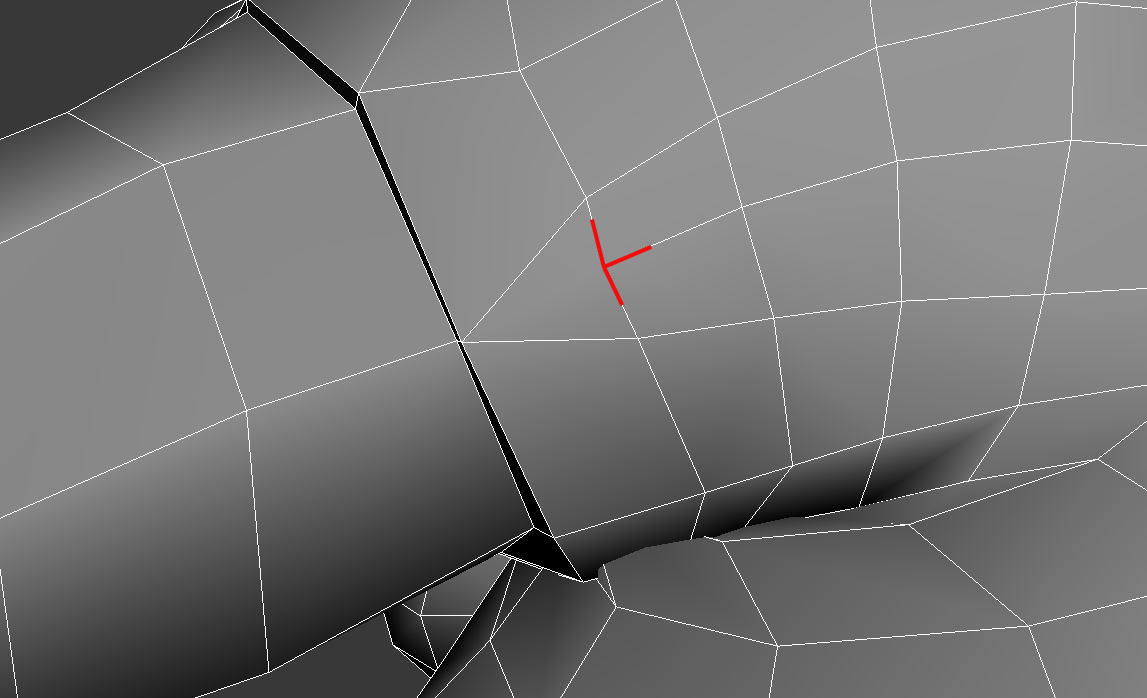
Unacceptable T-vertex
Any vertex with only three edges could be consider a T-vertex; the crossbar of the T doesn’t have to be straight across. You can use them when there’s no better solution, but it is best to avoid them as much as possible. Here, we’ll look at at few T-vert situations, both acceptable and unacceptable.
Flowing Around Corners – Acceptable
When a model’s shape changes direction, T-vertices are necessary where the quad flow from one direction meets the flow from the other direction.

On this rabbit model, an acceptable T-vertex forms where the edge flow up the side of the ear meets the edge flow across the top of the ear.
On cell phones and other electronics, an acceptable T-vertex forms when the quad flow from the side of the phone forms a corner with the flow across the bottom of the phone.
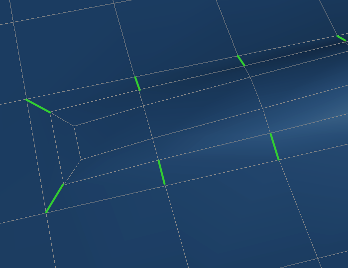
Insets – Acceptable
The method of creating extra detail described in the Oblong Cutouts video creates T-vertices. These vertices are acceptable because this method is the best way to increase detail within a specific area while still maintaining easily selectable edge loops.
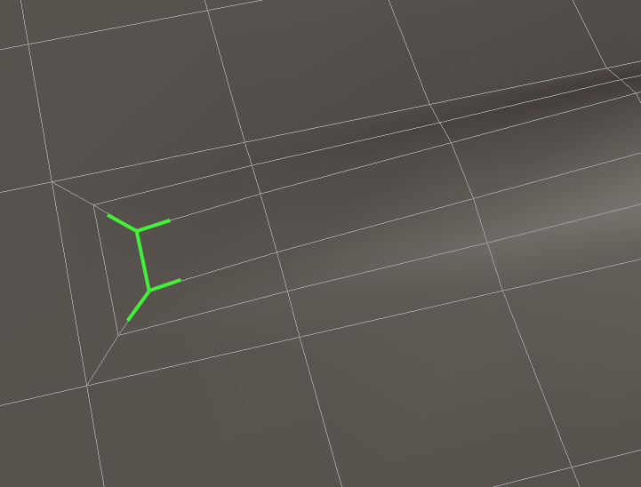
The recommended method for increasing detail creates acceptable T-vertices.
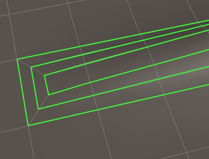
Such a construction is easy to edit. It results in easily selectable edge loops.
You (or the customer) can easily select rings of edges…
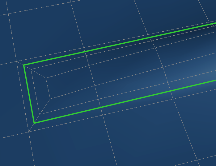
…and create a new set of edges by connecting the ring selection.
Transitioning with Other Methods – Usually unacceptable
Artists sometimes use T-verts as a solution for going from an area of high detail to lower detail. This is acceptable as long as the transition uses insets as described above. If insets are not used, the topology is probably not the best it can be, which means it fails CheckMate Pro v2. A straight T crossbar is often an indication of poorly planned topology.
A T-vertex with a straight crossbar is usually not the best solution.
It’s better to extend the edges…
…or make the sleeve and arm separate objects…
…or rearrange the edges so the inset method can be used.
Unnecessary Use of Inset Method – Unacceptable
Just because all your T-vertices are a result of insets, does not mean the model will pass CheckMate Pro v2. In order for insets to be acceptable, they must be necessary. The model below fails CheckMate Pro v2 not on T-vertices, but on unnecessary and excessive edges. When the edges were removed, the model kept exactly the same shape.
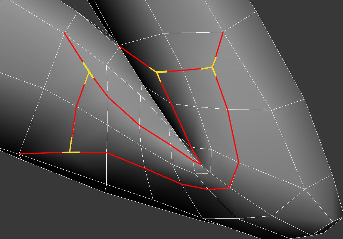
Although the T-vertices (yellow) are created with an inset structure, the red edges are unnecessary for this object and should be removed altogether.
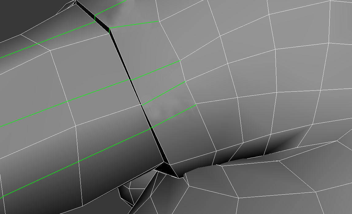
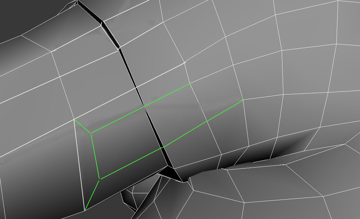
Bent Polygon – Unacceptable
A bent polygon can result from the use of T-vertices, with the polygon bending along a hidden edge following from the supporting bar of the T. This is poor topology that will cause undesirable effects in renderings.

Poorly planned T-vertices can result in a bent polygon.
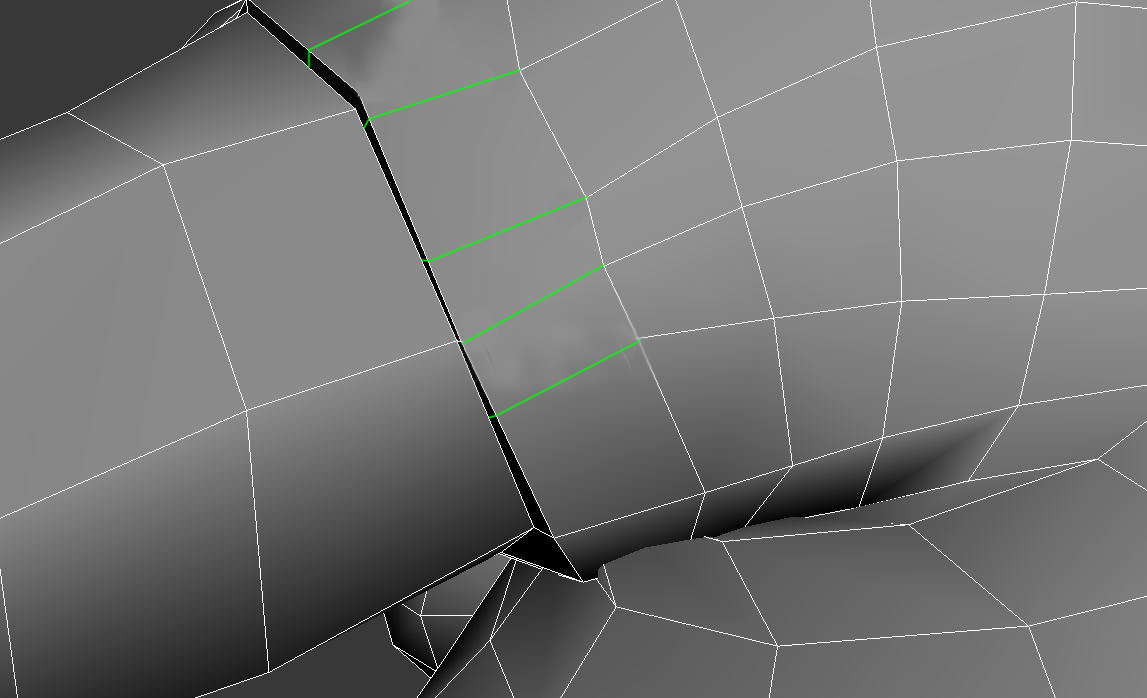
In this case, an edge should be added in place of the hidden edge, and the resulting topology should be adjusted for good edge flow.
These are just guidelines for T-vertices. As with all your topology, you should be constantly asking yourself, “Is there any way this could be better?” The existence of T-vertices in any situation other than the first two listed here is usually a sign that your topology could be (and should be) better.
If your model suffers from T-vertices and you don’t know how to fix them, you can submit your model for CheckMate Pro inspection and ask the inspector for assistance.